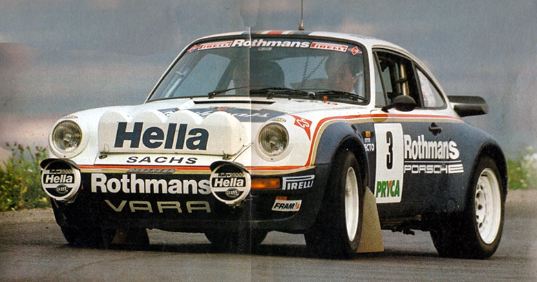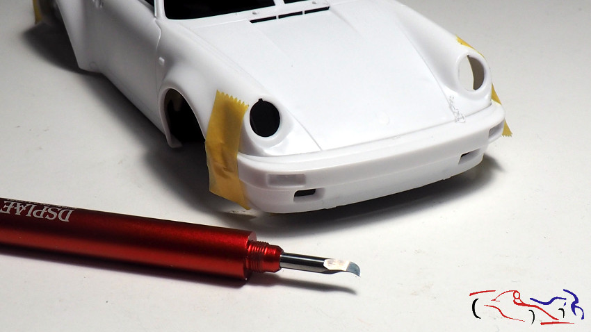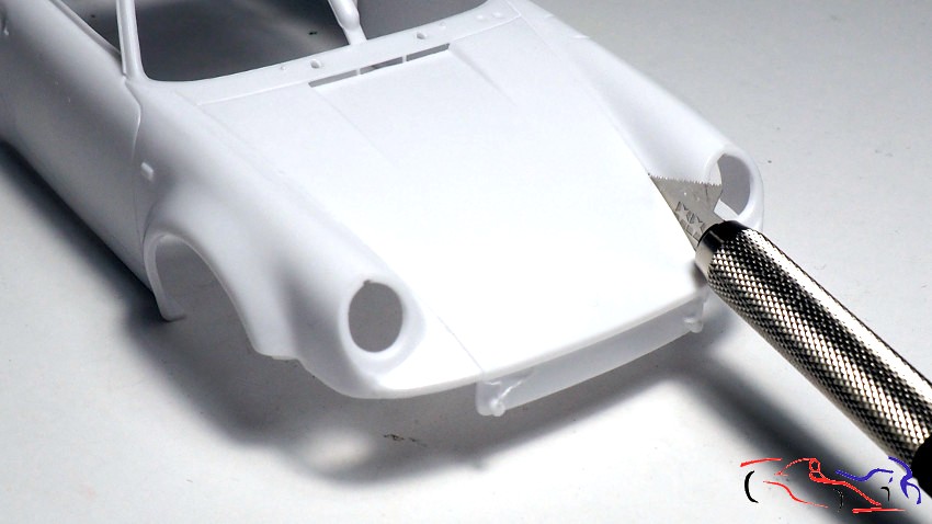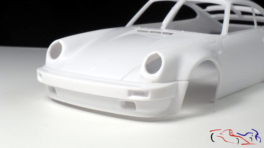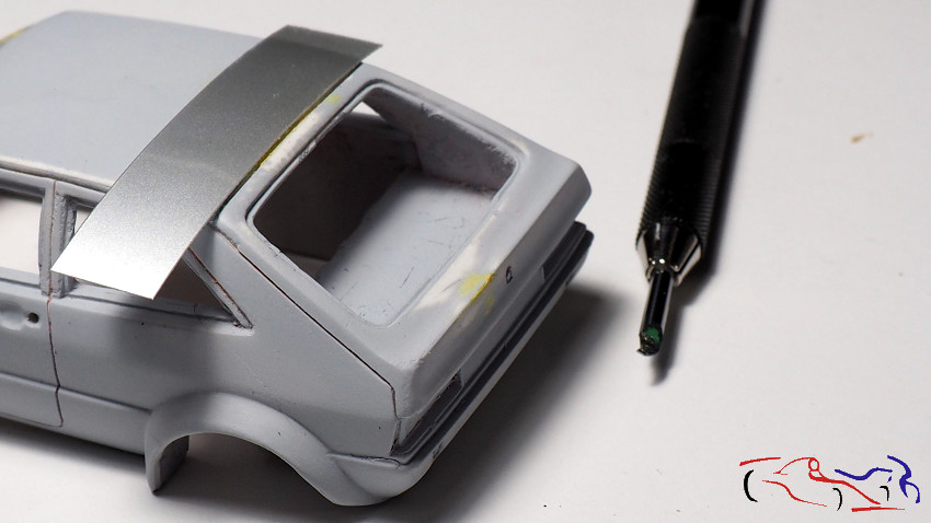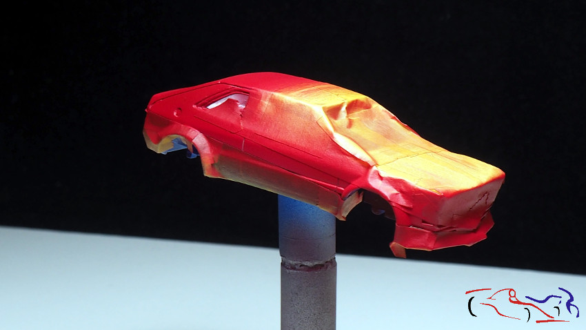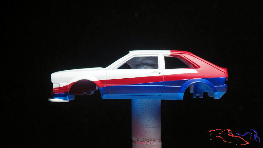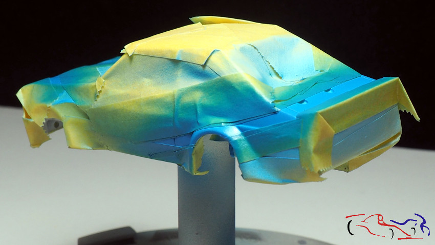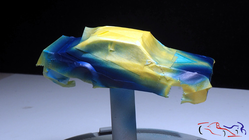
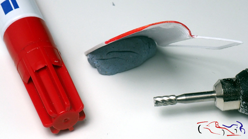
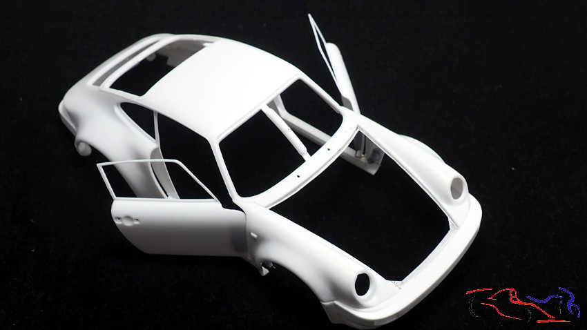
Continuamos con este Porsche, en concreto con todo el tema de las puertas, tanto con sus bisagras como con su adaptación en la cuna y en la carrocería. Y lo primero que hacemos es rebajar el borde de las puertas. Para ello pinto todo el borde con rotulador rojo, para así, ver lo que me queda rebajar cuando estoy con el minitaladro. Aquí os muestro como decrece el ancho en la parte derecha del borde de la puerta, estando el izquierdo sin tocar. Este frebaje dará más realidad a las puertas y permitirá que se muevan mejor por donde están las bisagras.
We continue with this Porsche, specifically with the whole issue of the doors, both with their hinges and their adaptation in the cradle and the body. And the first thing we do is to lower the edge of the doors. To do this I paint the entire edge with red marker, so I can see what I have left to lower when I’m with the mini drill. Here I show you how the width decreases on the right side of the door edge, being the left one untouched. This will give more reality to the doors and will allow them to move better where the hinges are.
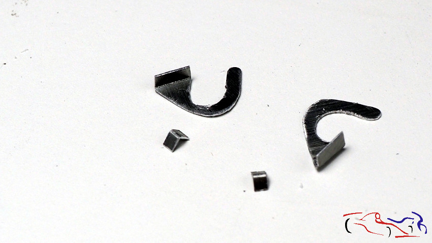
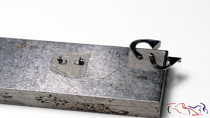
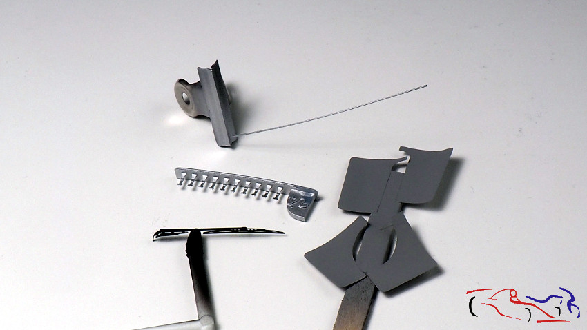
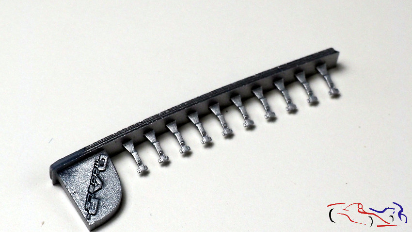
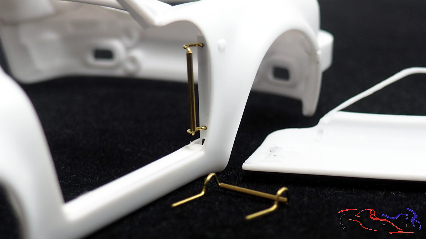
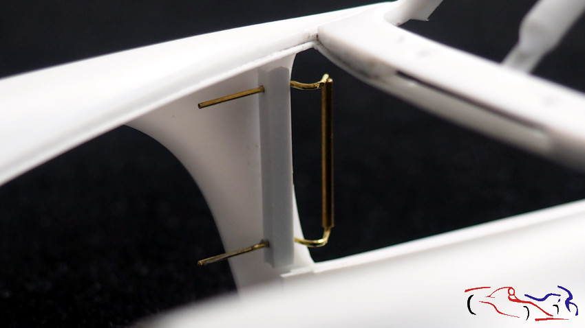
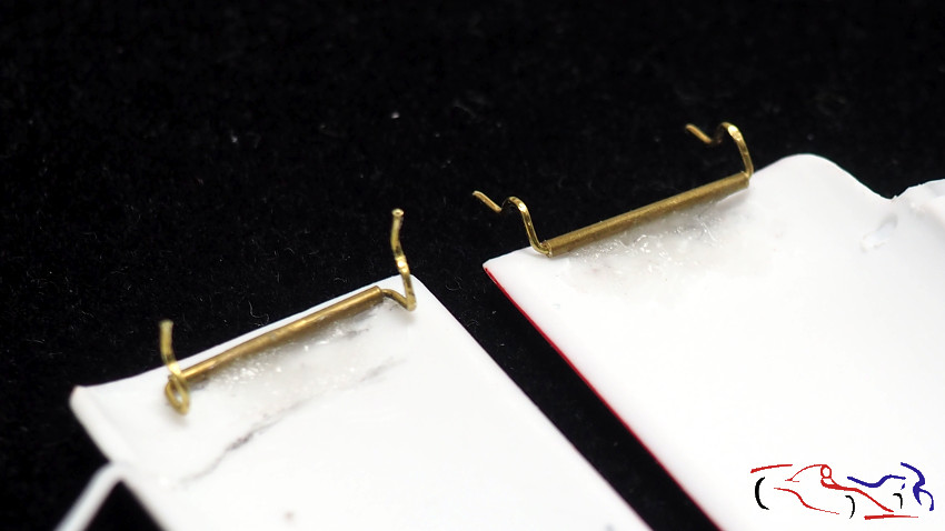
Y hablando de bisagras, aquí las teneís. Realizadas con tubo en el que inserto un alambre de 0,4 mm para que gire. Este alambre lo doblo de la forma que veis en las fotos dejaando el tubo exterior en el lado de la puerta, para que al abrirse la puerta, su extremo delantero se meta haca el interior de la carrocería, en los huecos que el alambre le permite. Los extermos del alambre, los metemos en una barra de plastico en sendos agujeros y que fijamos a la carrocería. Probamos como funciona, fijando la bisagra a la puerta con bluetack.
And speaking of hinges, here you have them. Made with a tube in which I insert a 0.4 mm wire to rotate. This wire I bend it in the way that you see in the photos leaving the outer tube on the side of the door, so that when the door opens, its front end gets inside the body, in the holes that the wire allows. The extermos of the wire, we put them in a plastic bar in two holes and that we fix to the bodywork. We test how it works, fixing the hinge to the door with bluetack.
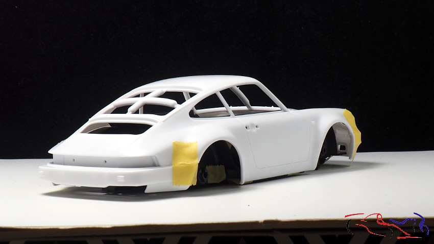
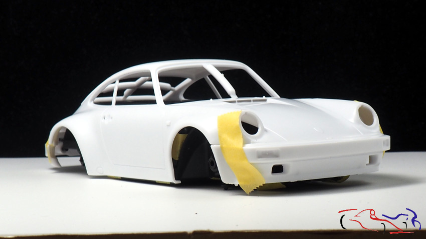
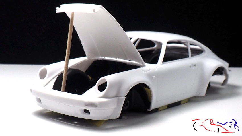
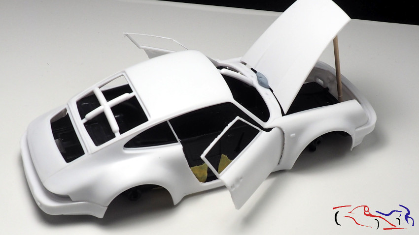
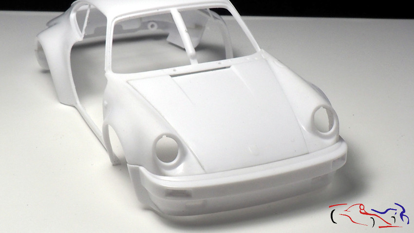
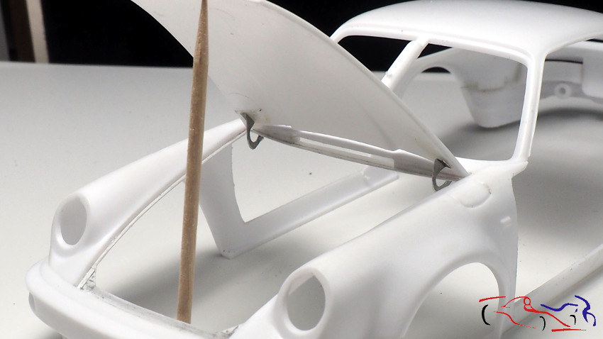
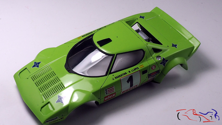
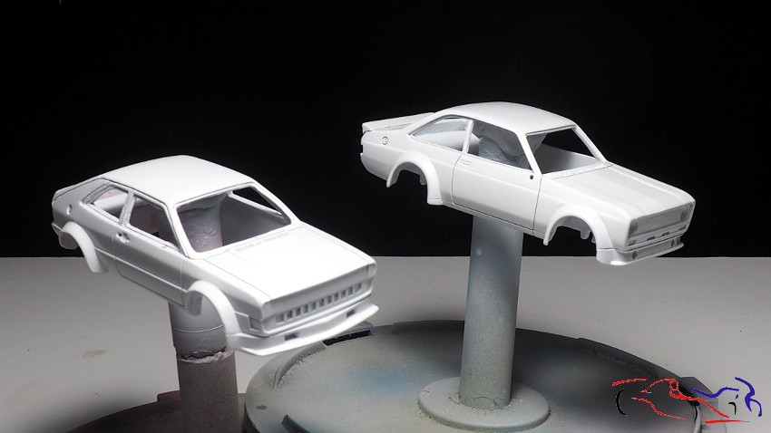
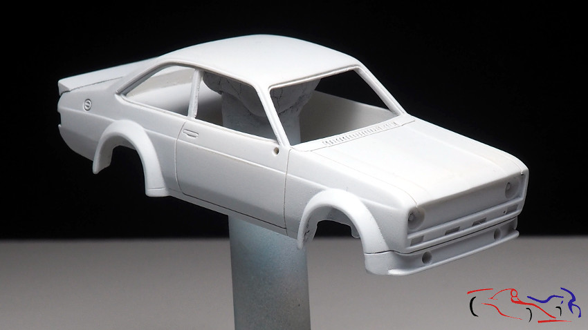
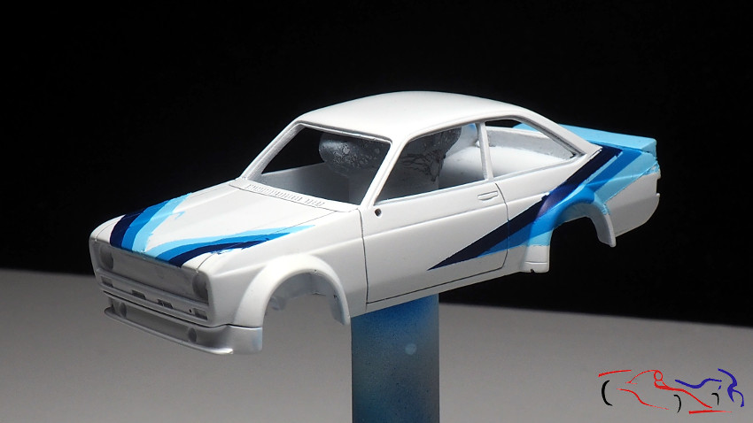
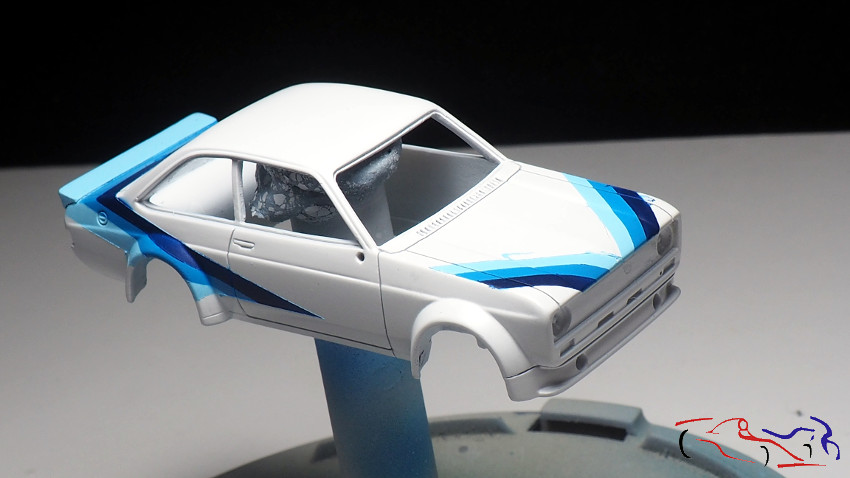
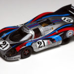
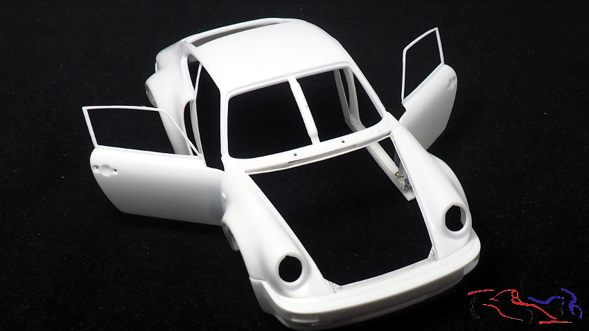
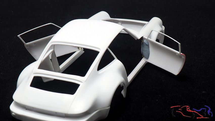
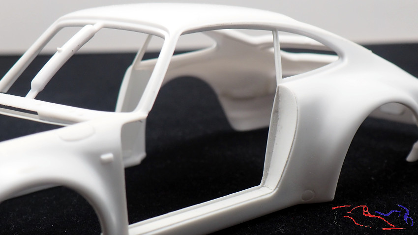
Y así se ve la carrocería con las puertas abiertas:
And this is what the bodywork looks like with the doors open:
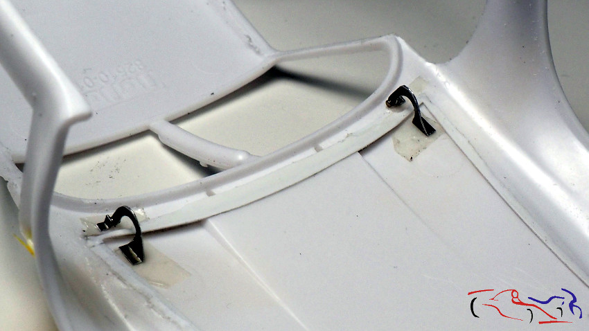
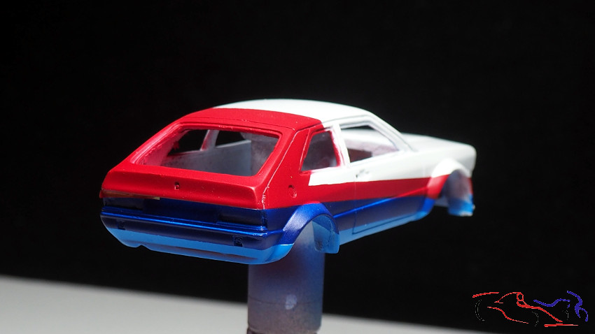
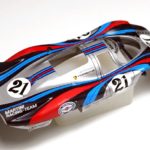
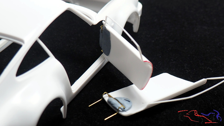
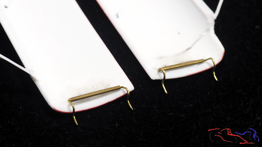
Una vez que hemos comproado su fucionamiento, las fijamos en la carrocería con cinta de enmascarar, y pegamos la bisagra a la puerta, con cianocrilato mezclado con polvos de talco, para hacer el pegamento más consistente, siendo éste el resultado:
Once we have checked their operation, we fix them to the bodywork with masking tape, and glue the hinge to the door, with cyanoacrylate mixed with talcum powder, to make the glue more consistent, and this is the result:
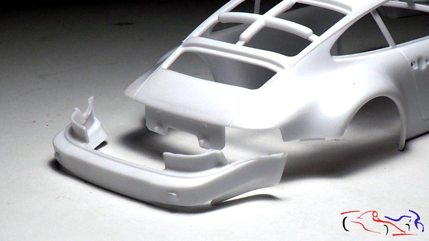
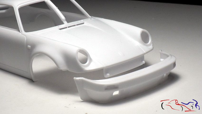
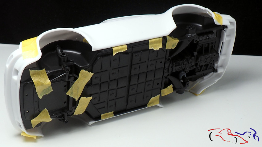
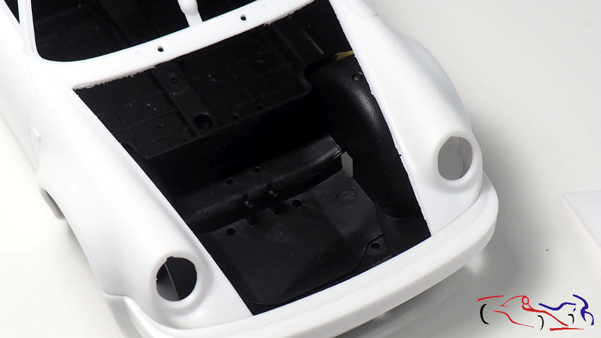
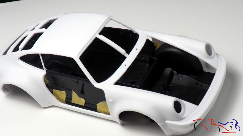
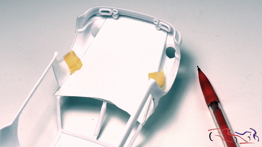
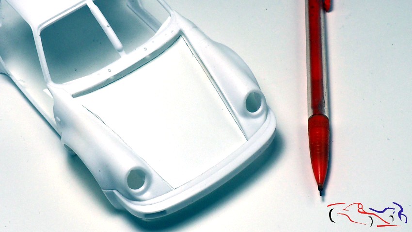
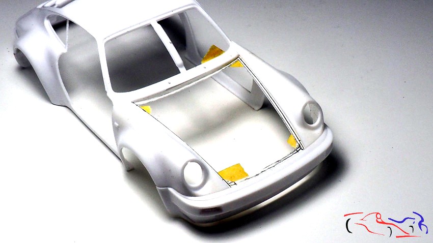
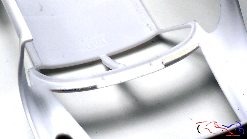
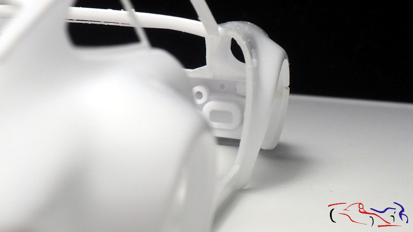
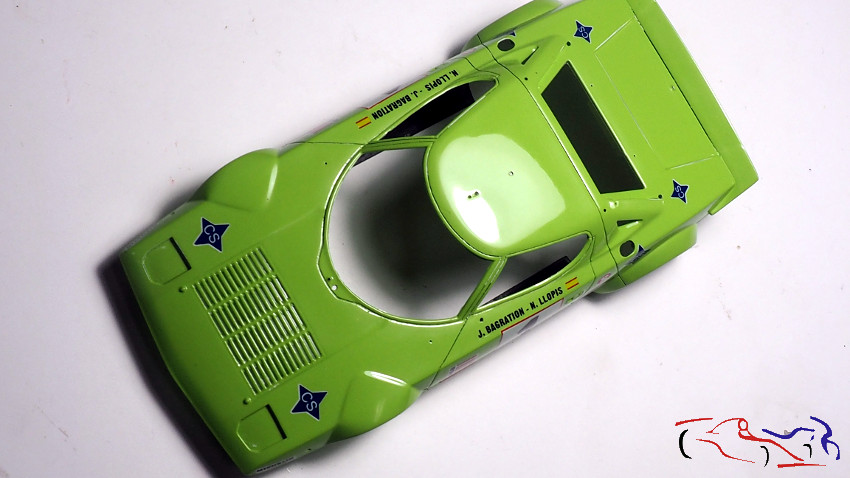
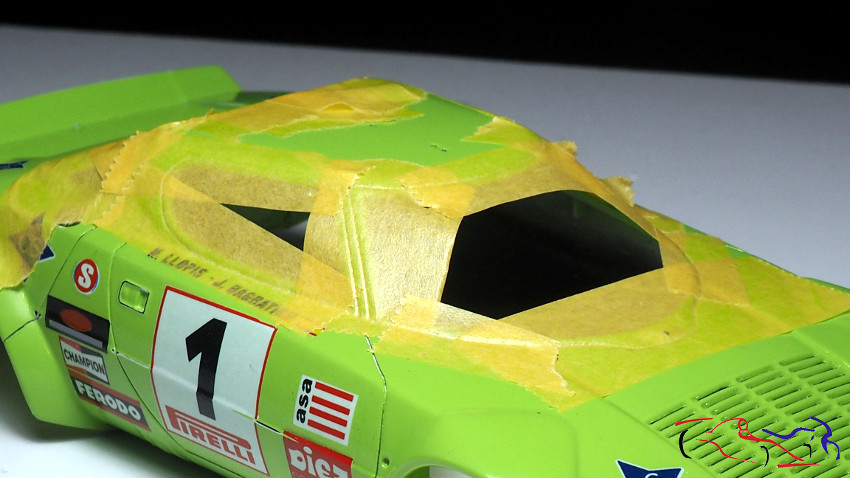
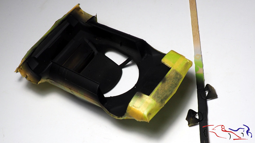
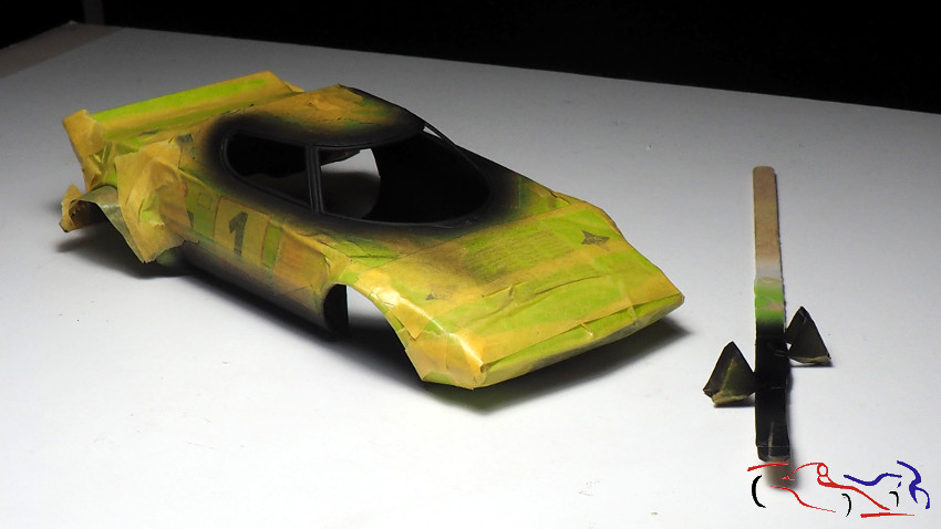
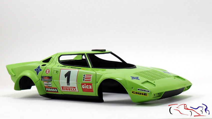
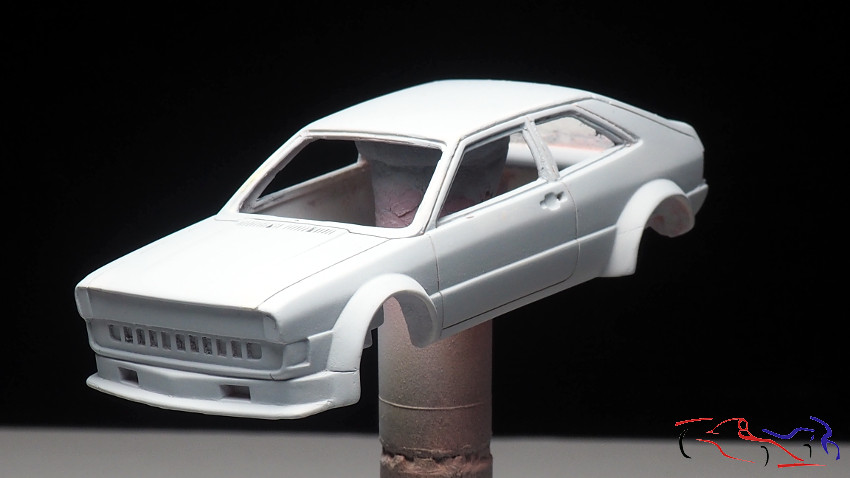
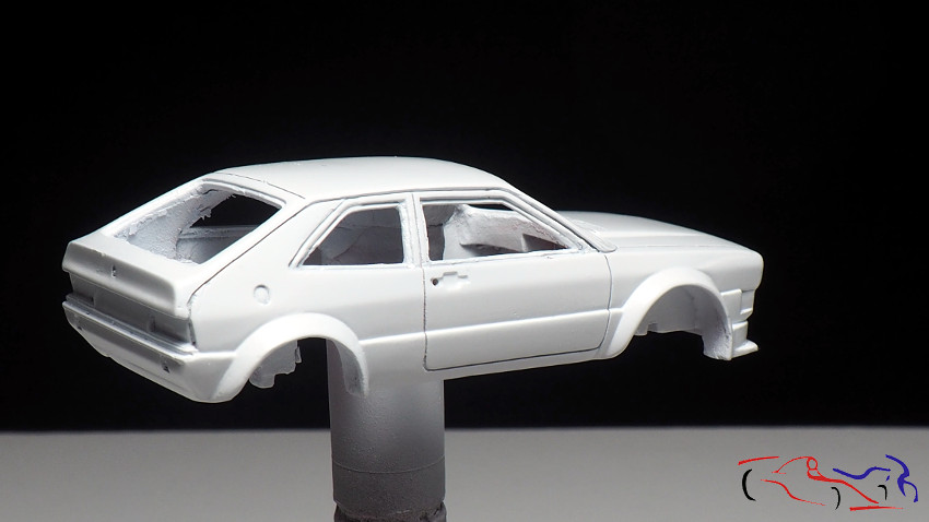
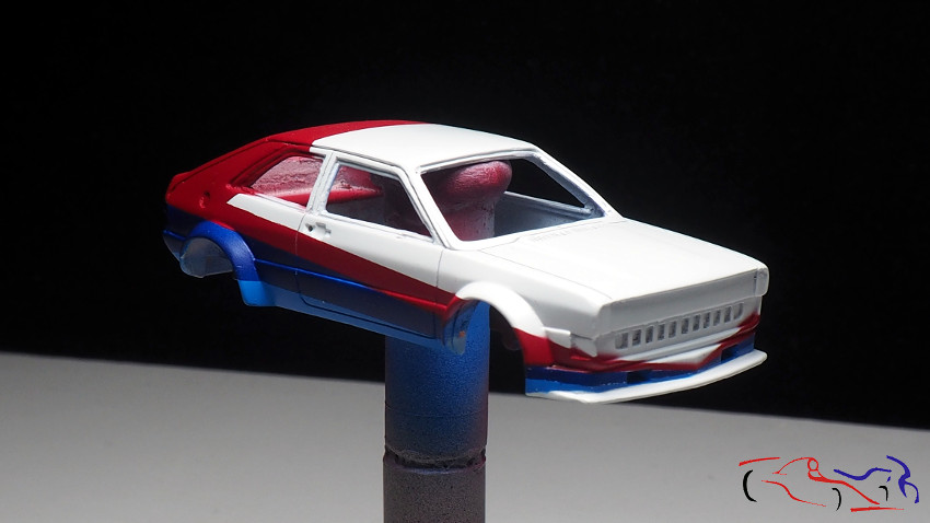
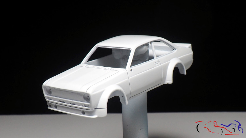
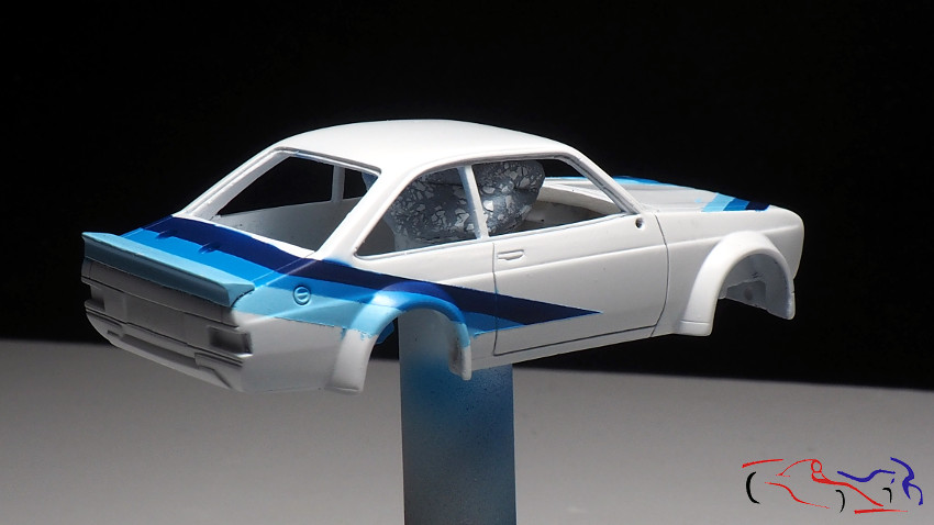
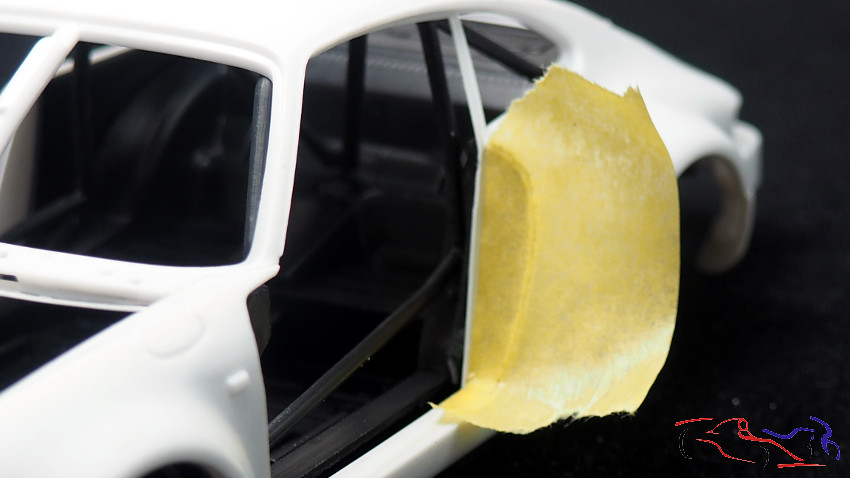
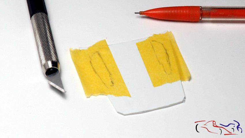
Y ya nos ponemos a completar la carrocería y la cuna del cockpit de acuerdo a las fotografias reales y dentro de lo que el kit nos deja. Y lo primero es rellenar el hueco de la carrocería. Ponemos cinta de enmascarar, pintamos el hueco con un lapiz, recortamos y pegamos. También, hemos colocado el reborde por todo el marco d ela puerta donde irá la tira de goma que hará estanco el habitáculo cuando la puerta esté cerrada.
And now we start to complete the bodywork and the cockpit cradle according to the real pictures and within what the kit leaves us. And the first thing is to fill the hole in the bodywork. We put masking tape, paint the hole with a pencil, cut and paste. Also, we have placed the flange around the door frame where the rubber strip that will make the cabin watertight when the door is closed.
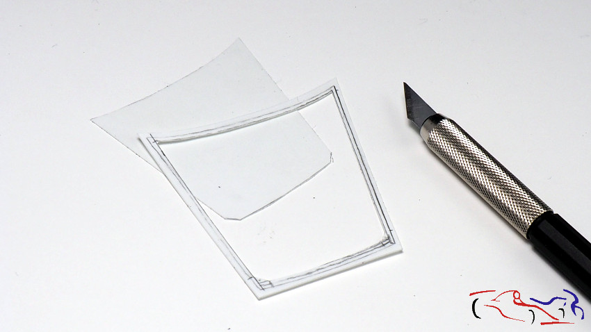
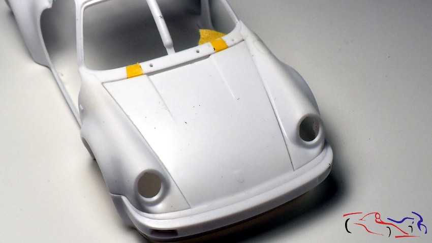
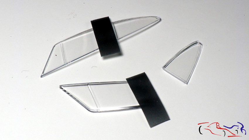
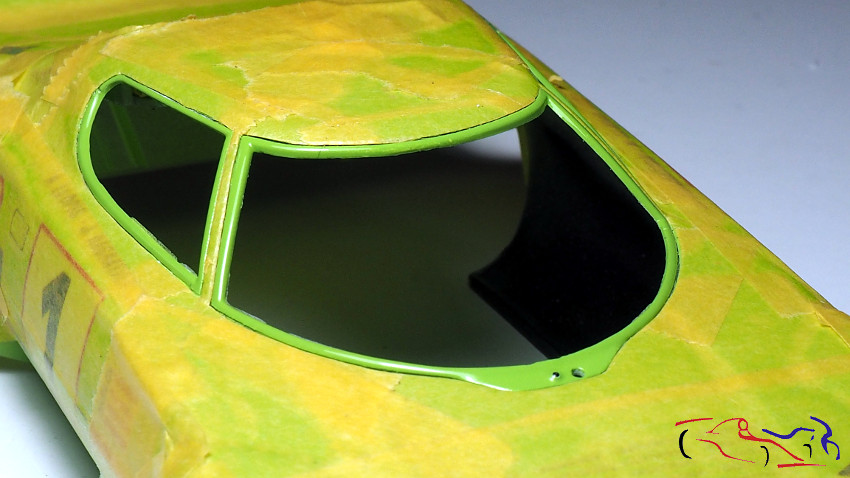
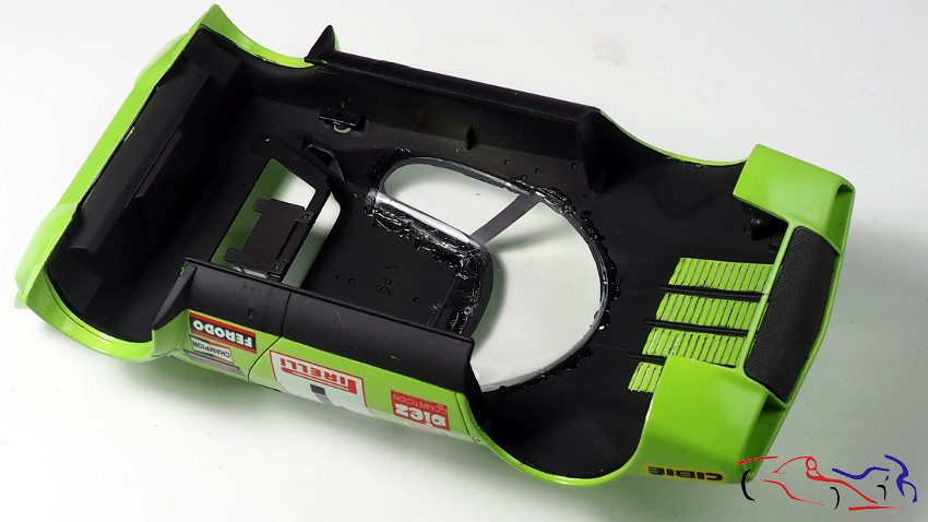
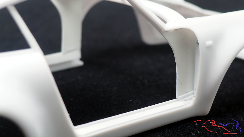
En la siguiente foto, vemos la parte correspondiente a la parte baja y delantera de la puerta, con los trozos de plastico que han rellenado los huecos que se ven al recortar la puerta de la carrocería.
In the following photo, we see the part corresponding to the lower and front part of the door, with the pieces of plastic that have filled the holes that are seen when trimming the door of the body.
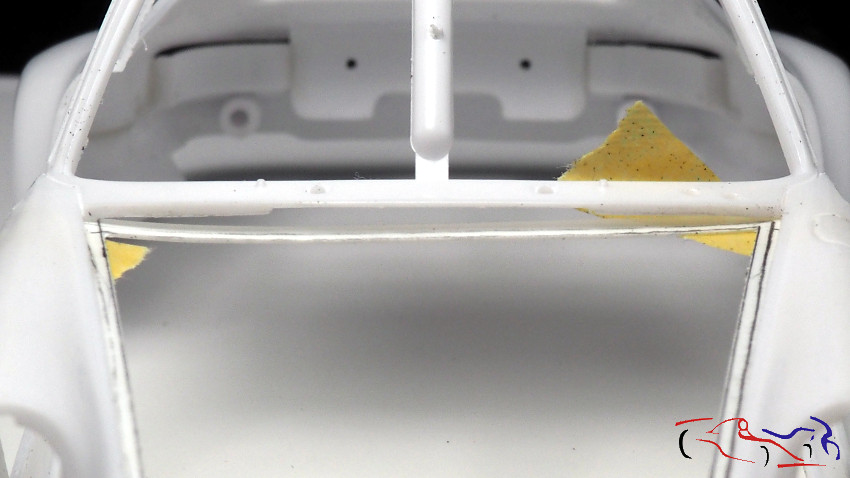
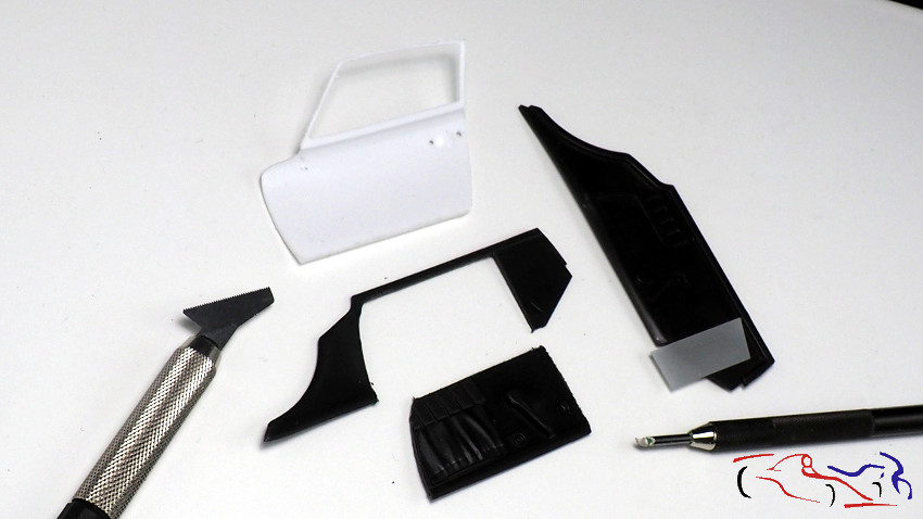
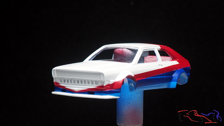
Y la cuna también a tenido que ser recortada para tener el panel interior de las puertas que tendremos que adaptar. Si veis, el apnel lateral se ah recortado por delante dejando los pivotes donde se sujetará el salpicadero. Decir, que ya están pegados a la cuna.
And the cradle also had to be trimmed to have the inner panel of the doors that we will have to adapt. If you see, the side apnel ah ah cut in front leaving the pivots where the dashboard will be attached. To say that they are already glued to the cradle.
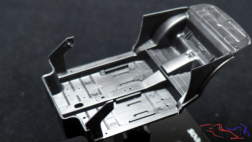
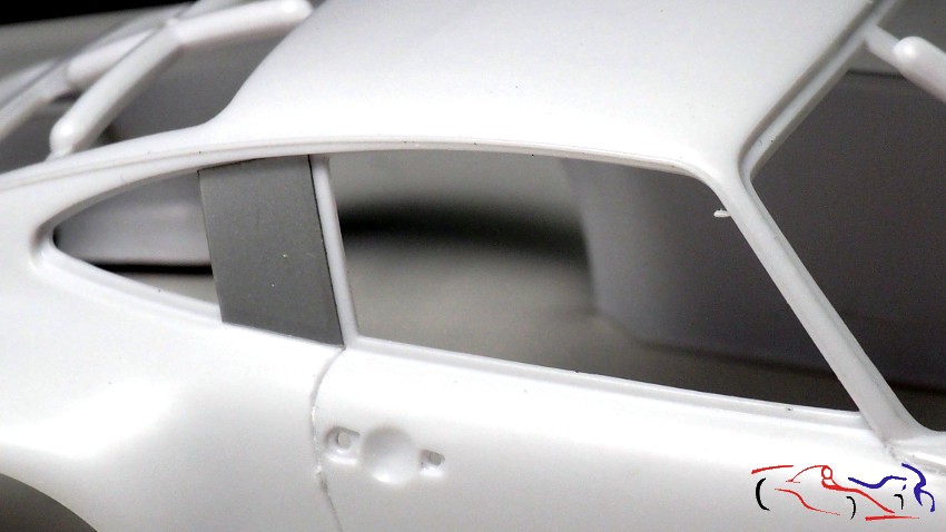
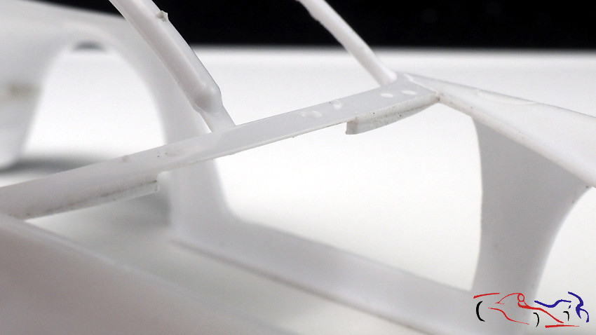
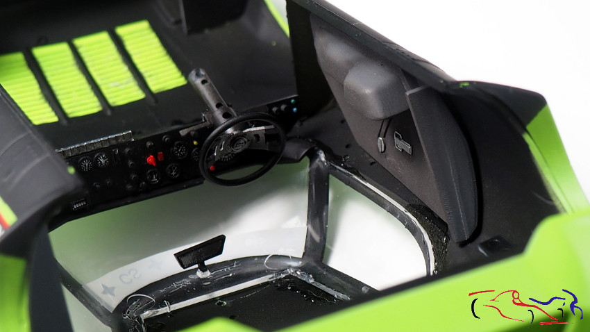
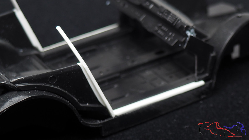
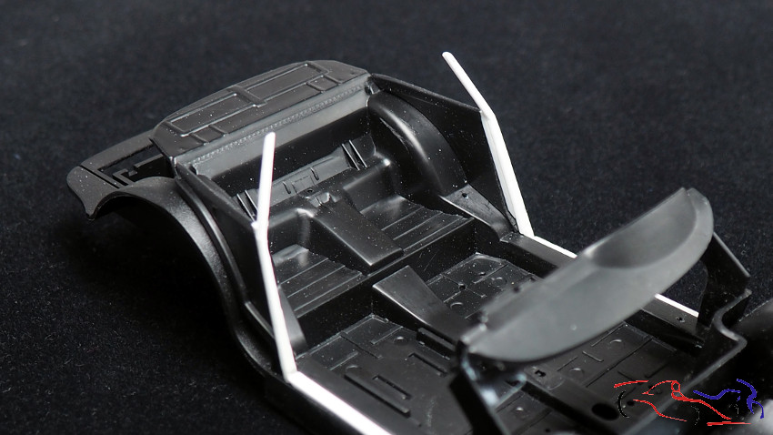
Y al cortar, hay que adaptar y rellenar los huecos. Empezamos por los laterales horizontales de las puertas. Después seguimos con esas piezas casi verticales, que tienen la forma interior del pilar B, y que van pintadas de negro. Esto lo podía haber pegado a la carrocería pero al ser negro, lo añado a la cuan, y se quedará junto al pilar B cuando lo pongamos dentro d ela carrocería. También vemos como va colocado el salpicadero, sujeto con bluetack.
And when cutting, it is necessary to adapt and fill the gaps. We start with the horizontal sides of the doors. Then we continue with those almost vertical pieces, which have the inner shape of the B-pillar, and are painted black. This could have been glued to the body but being black, I add it to the quan, and will stay next to the B-pillar when we put it inside the body. We also see how the dashboard is placed, attached with bluetack.
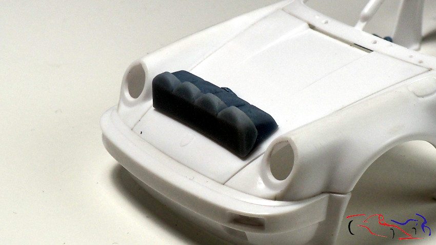
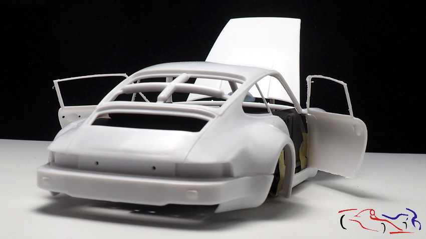
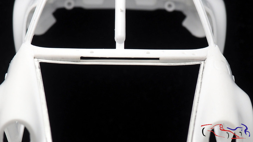
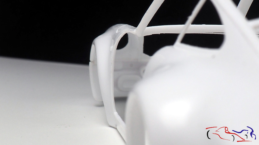
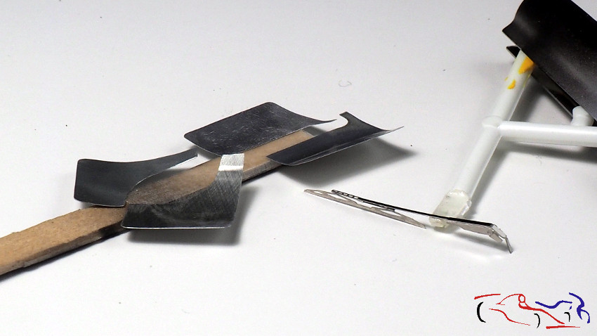
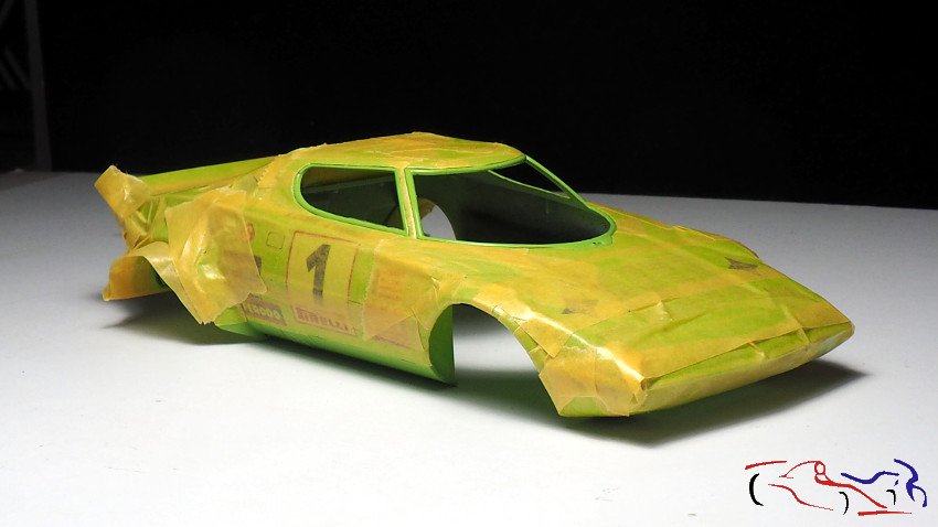
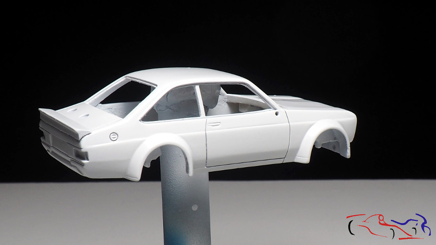
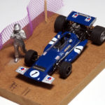
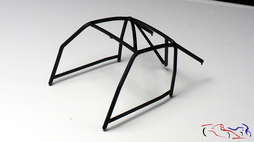
Y para terminar hoy, una foto del arco de seguridad, ya pegado a falta de detallar.
And to finish today, a photo of the safety arch, already glued and still to be detailed.
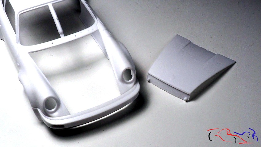
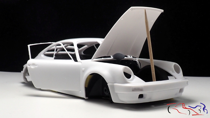
La siguiente fase será el detallado del capó antes de meterme con la masilla para afinar todo lo realizado hasta ahora. Gracias por ver y comentar!!
The next phase will be the detailing of the hood before I get into the putty to fine tune everything done so far. Thanks for watching and commenting!