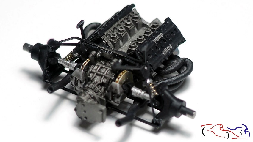
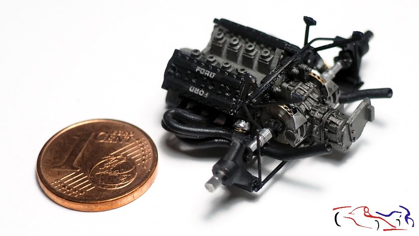
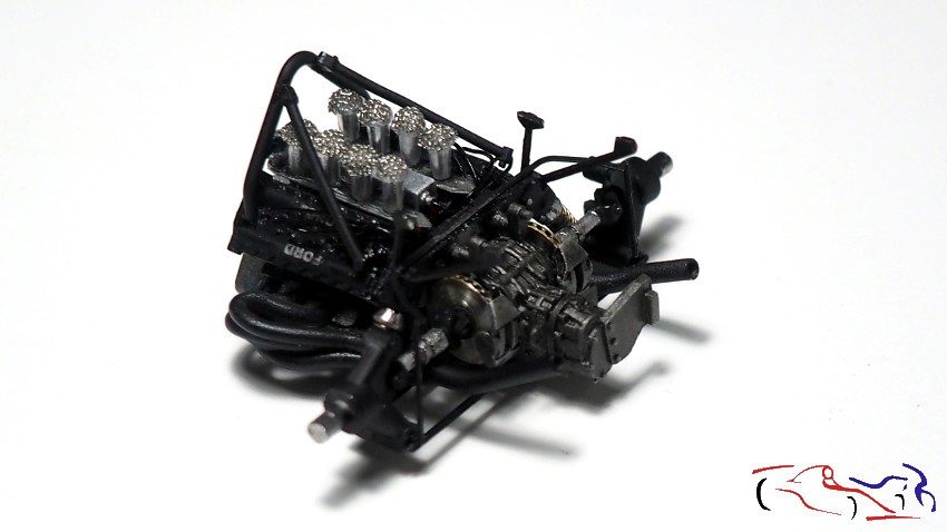
Hola a todos. Actualizo este proyecto, prinicpalmente porque ya realicá la fase de lacado de la carrocería, junto con los otros dos Porsches que tengo en proceso. Pero antes de la carrocería, vamos a hablar del motor. En el ultimo post, lo dejé con el bloque, la caja de cambios y las culatas. Desde entonces, he ido añadiendo los escapes y los ejes traseros con sus discos y soportes. Aquí lo veís comparando su tamaño con el de un cétimo de Euro:
Hello everyone. I’m updating this project, mainly because I’ve already finished painting the body, along with the other two Porsches I have in progress. But before the body, let’s talk about the engine. In the last post, I left off with the block, gearbox, and cylinder heads. Since then, I’ve been adding the exhaust system and the rear axles with their discs and mounts. Here you can see it compared to the size of a one-cent Euro coin:
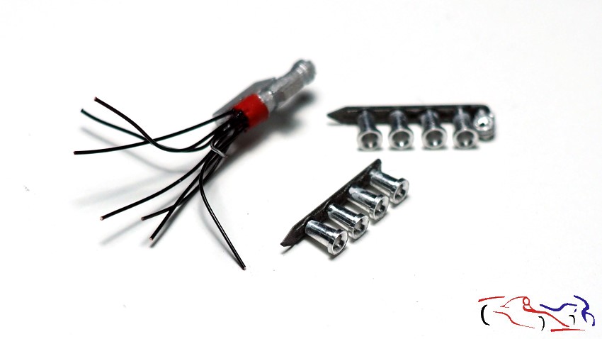
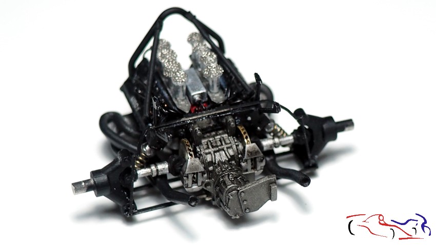
Y vamos a ir añadiendo partes: las trompetas de adminión y los cables de las bujias. Decir, que los cables no estában incluidos en el kit, y decidí ponerlos, practicando agujeros en las culatas, y en el distribuidor o “delco”:
And we’ll continue adding parts: the intake trumpets and the spark plug wires. I should mention that the wires weren’t included in the kit, so I decided to add them myself, drilling holes in the cylinder heads and the distributor.
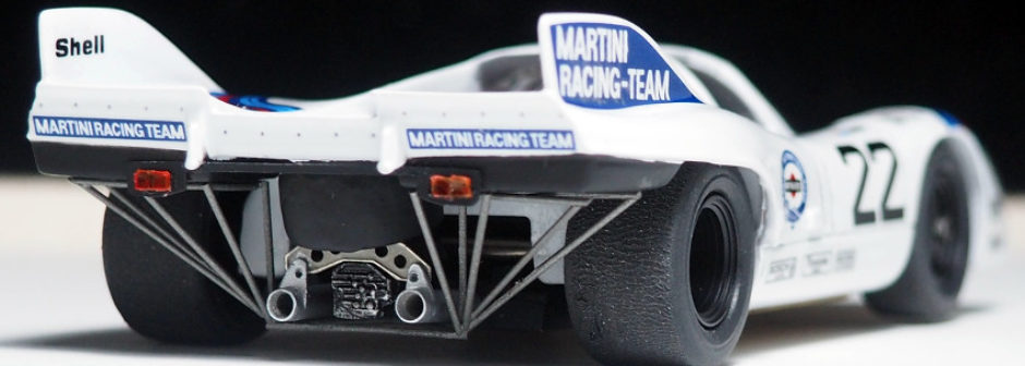
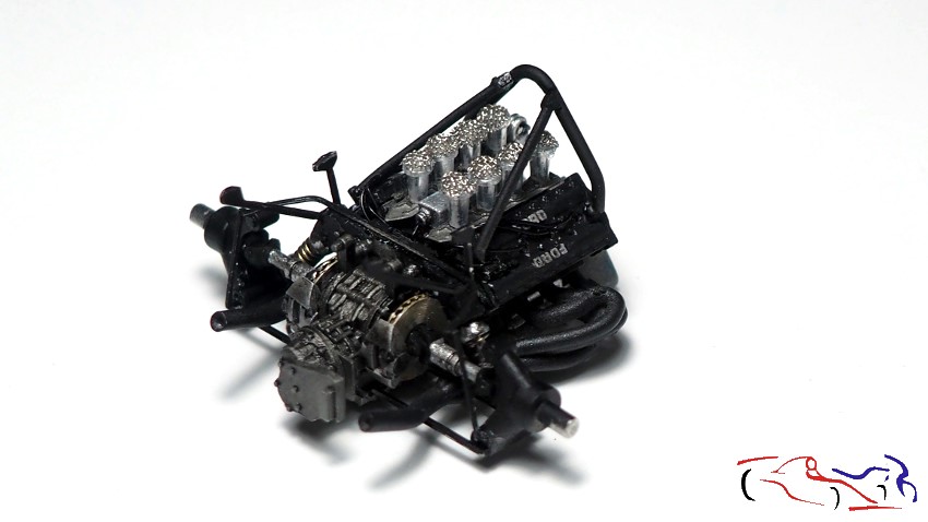
En las siguientes fotos, ya están añadidas las trompetas de admisión con sus filtros superiores, el “delco” con los cables colocados en las culatas, y las barras de seguridad del piloto:
In the following photos, the intake trumpets with their upper filters, the distributor with the cables placed in the cylinder heads, and the rider’s safety bars have already been added:
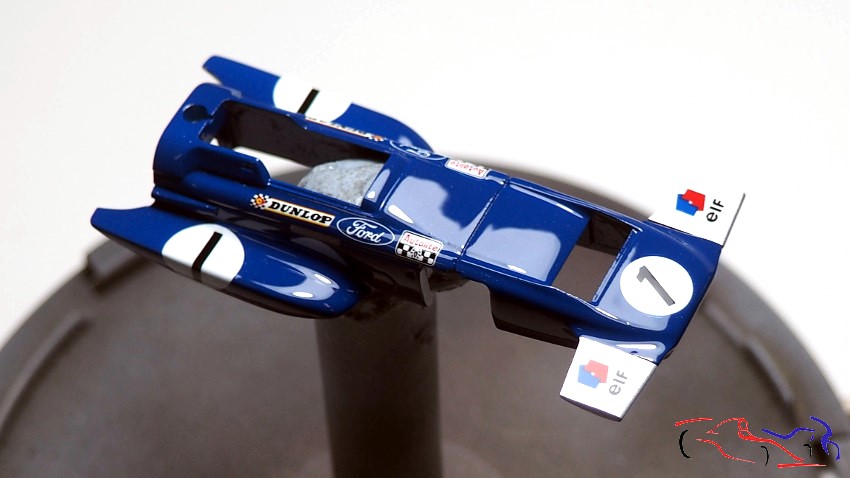
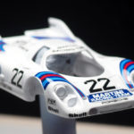
Y ahora si, pasamos a la carrocería. Se lacó con Number5: dos capas muy ligeras y una última capa más cargada, con un poco más de disolvente. EL resultado es magnífico como podéis observar:
And now, let’s move on to the bodywork. It was lacquered with Number 5: two very light coats and a final, thicker coat with a bit more thinner. The result is magnificent, as you can see:
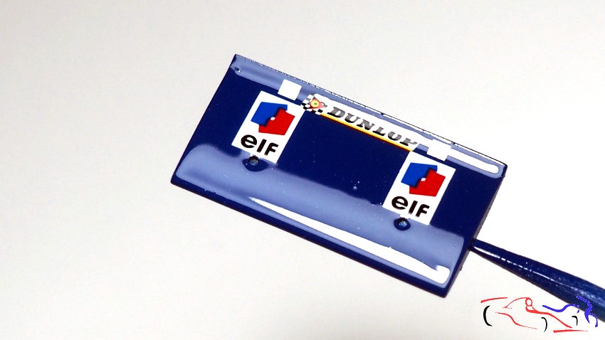
El único pero que he tenido ha sido una mota de polvo que se pegó en el alerón, entre las dos pegatinas de Elf. Tocará lijar y pulir!!
The only problem I’ve had is a speck of dust that got stuck to the spoiler, between the two Elf stickers. It’ll need sanding and polishing it!
En el próximo post, os mostraré los pasos siguientes, antes de terminar con las fotos finales y el diorama!! Gracias por ver y comentar!!
In the next post, I’ll show you the next steps before finishing with the final photos and the diorama! Thanks for watching and commenting!
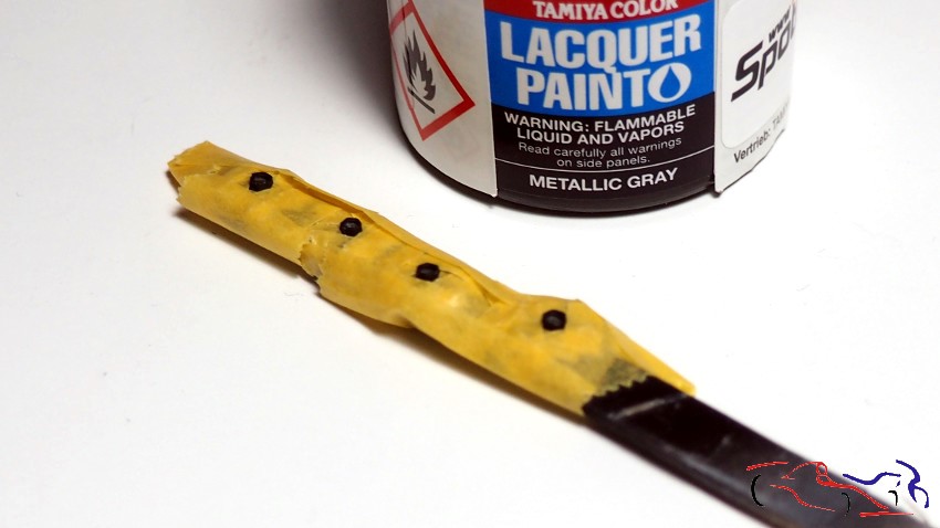
Hola a todos. Continuamos con este kit, que estoy haciendo al mismo tiempo que el otro Porsche 917 y que el March 701. En primer lugar, os muestro el trabajo realizado con las llantas. Una vez pintadas de negro semi mate LP de Tamiya, enmascaro las tuercas y las pinto con el gris metálico LP de Tamiya. El resultado lo veremos en el siguiente post:
Hello everyone. We’re continuing with this kit, which I’m working on at the same time as the other Porsche 917 and the March 701. First, I’ll show you the work I’ve done on the wheels. Once painted with Tamiya LP semi-matte black, I masked off the lug nuts and painted them with Tamiya LP metallic gray. We’ll see the result in the next post.
Pasamos al chasis. Esta pieza la vamos a pintar de gris, con el ventilador en color Kevlar de Zero, y el negro semi mate LP de Tamiya. Los asientos, los cinturones y las barras están pintados a pincel con colores Vallejo, y le he aplicado a todo el conjunto, unos lavados de Panel Liner negro de Tamiya:
Now we move on to the chassis. We’re going to paint this part gray, with the fan in Zero Kevlar paint and Tamiya LP semi-matte black. The seats, seatbelts, and bars are hand-painted with Vallejo colors, and I’ve applied washes of Tamiya Panel Liner black to the whole assembly.
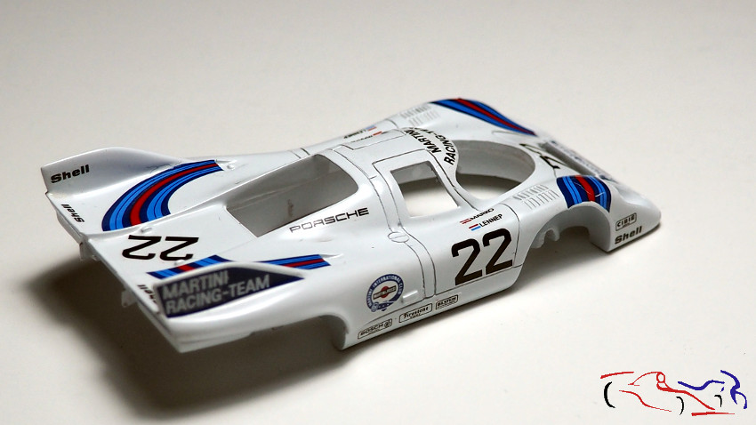
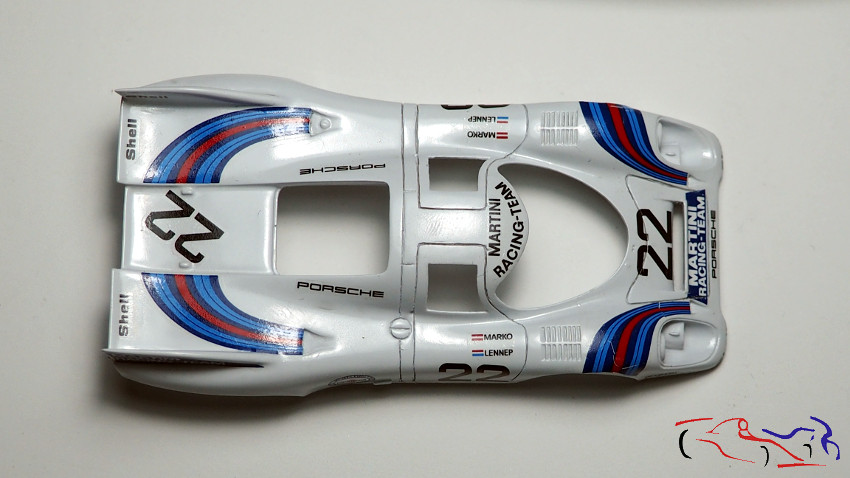
Y ahora, es el turno de la carrocería. La pintamos con el blanco Numer5 sobre la imprimación de Gravity:
And now, it’s the body’s turn. We painted it with Numer5 white over Gravity primer:
Y después de una capa de Future, empiezo a aplicar las calcas, con mucho cuidado, con mucho líquido, y mucho calor, porque son muy duras y viejas. También le aplico el pegamento de calcas de Tamiya.
After applying a coat of Future primer, I start applying the decals very carefully, using plenty of fluid and a lot of heat, because they are very hard and old. I also apply Tamiya decal adhesive.
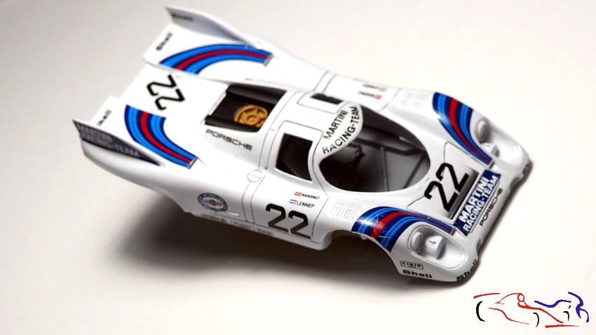
Y después de pasar mucho tiempo con estas pocas calcas, tenia que ver la carrocería con el chasis!!
And after spending a lot of time with these few decals, I had to see the bodywork match the chassis!
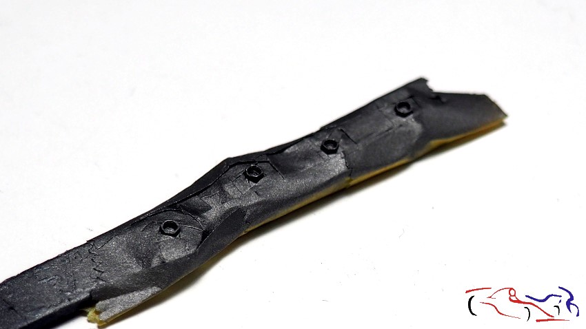
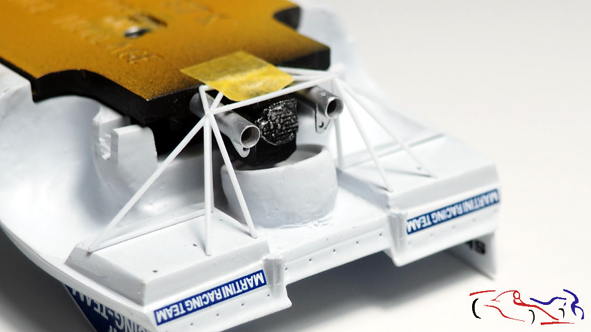
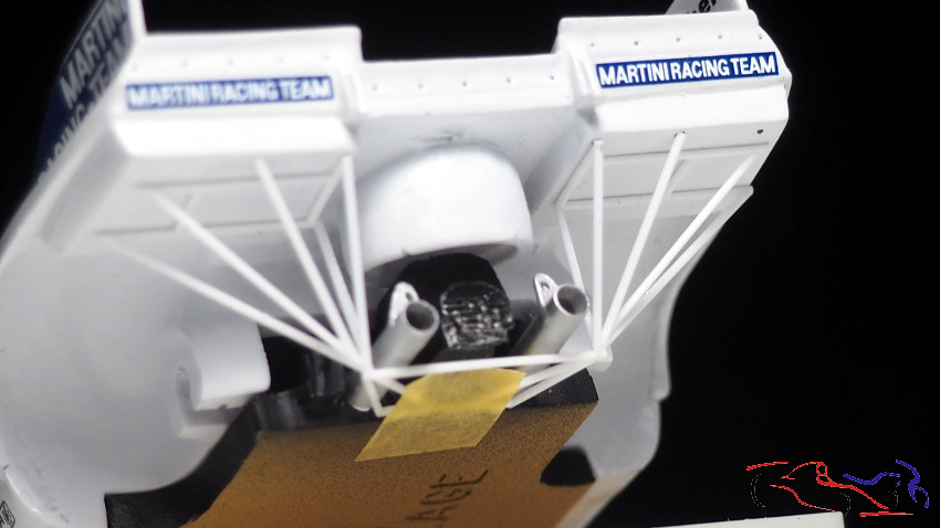
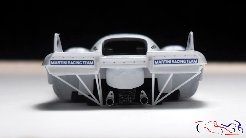
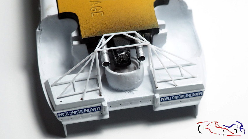
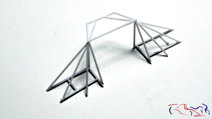
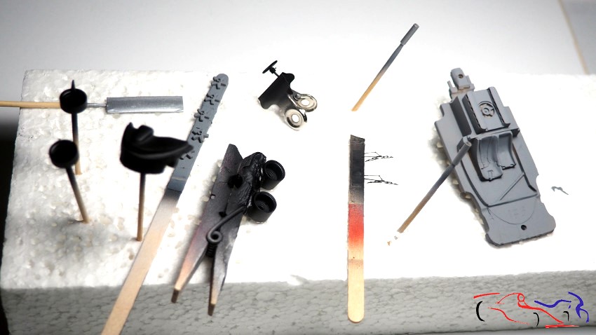
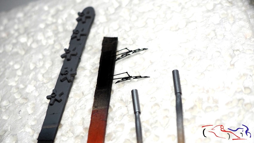
En la parte trasera, el entramado tubular que tare el kit es un poco escaso y complicado, con 3 fotograbados. Los desecho y decido hacerlo yo con varilla de 0,5 mm. El proceso empezó con las varillas que están debajo de la cinta de enmascarar en la primera foto, y continuó pogando el resto de varillas. Lo hice sobre una base de cristal, ya que el pegamento de Tamiya del tapón verde claro, no le afecta, y se puede separar sin problema. En la primera foto, también podéis ver los tubos de escape metálicos, con sus fijaciones realizadas posteriormente con plástico.
At the rear, the tubular frame included in the kit is a bit sparse and complicated, with only three photo-etched parts. I discarded them and decided to make it myself using 0.5mm rod. The process began with the rods visible under the masking tape in the first photo, and continued with the remaining rods. I worked on a glass base, as the Tamiya glue on the light green cap doesn’t affect it, and it can be easily removed. In the first photo, you can also see the metal exhaust pipes, with their mountings added later using plastic.
Esta pieza irá pintada en negro semi mate, pero eso será en el próximo post. Gracias por ver y comentar!!
This piece will be painted in semi-matte black, but that will be in the next post. Thanks for watching and commenting!
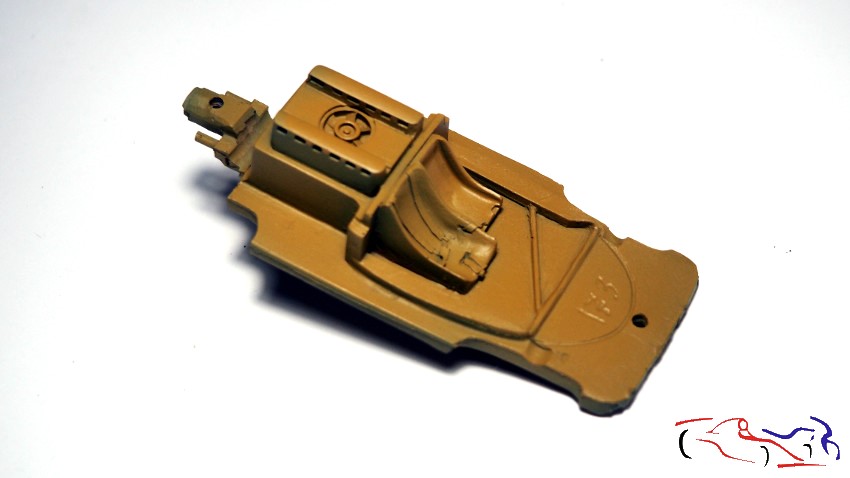
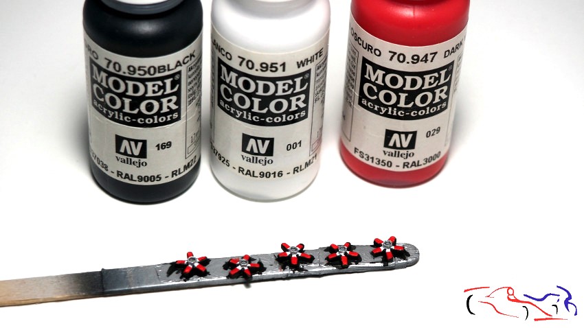
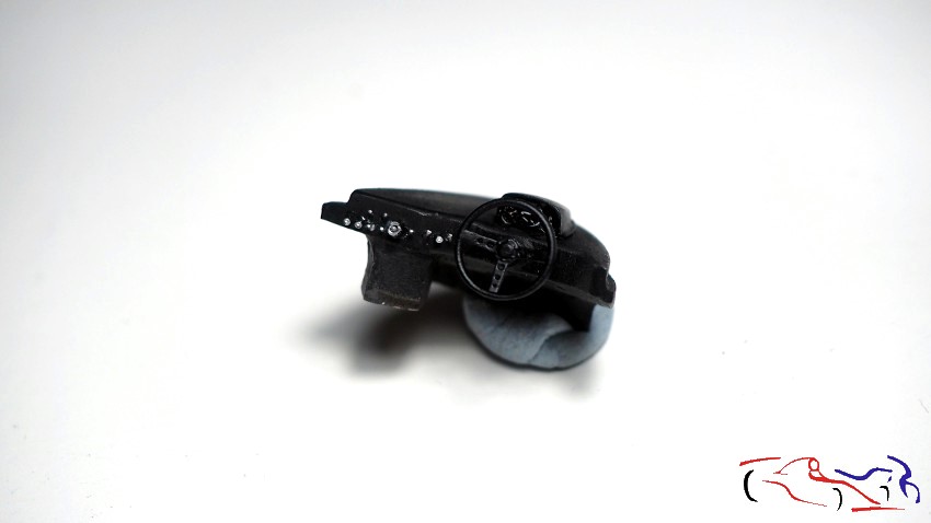
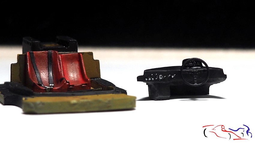
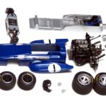
Hola a todos de nuevo! Continuamos con este Porsche “cola larga”, y comenzamos por lo que “no es carrocería”: chasis, salpicadero y las piezas que hacen de llantas. En el chasis, lo pintamos con el color Kevlar de Zero Paints. El salpicadero lo pintamos de negro, le ponemos un volante de DAB Models, los interruptores, y una calca para el reloj. Y respecto a los embellecedores de las llantas, las pintamos con una rayita de blanco en cada radio, el resto del radio de rojo, con la base de negro. Dejo el salpicadero en grande porque tiene mas detalle, aunque pulsando en las fotos, se muestran en mayor tamaño.
Hello everyone again! We’re continuing with this “long-tail” Porsche, and we’ll start with what “isn’t the body”: the chassis, dashboard, and the wheel trim pieces. We painted the chassis with Zero Paints’ Kevlar color. The dashboard was painted black, fitted with a DAB Models steering wheel, switches, and a decal for the clock. As for the wheel trim, we painted each spoke with a white stripe, the rest of the spoke red, and a black base. I’ve included a large image of the dashboard because it has more detail, although clicking on the photos will display them in a larger size.
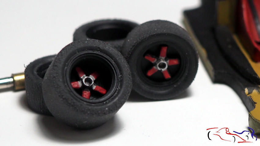
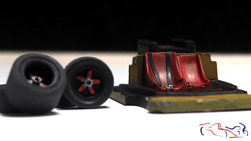
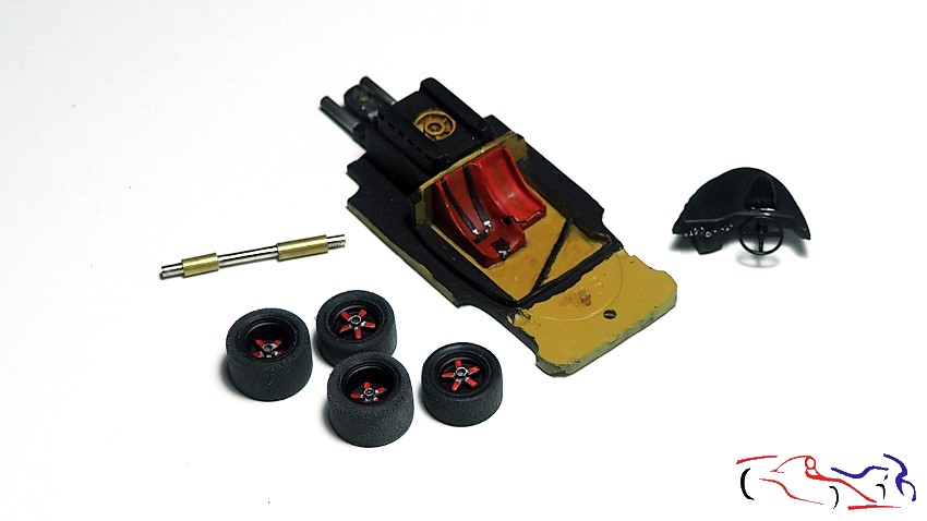
Así, el resultado de todo se ve en las siguientes fotos. Destacar que las llantas van pintadas de negro semi mate LP de Tamiya, los asientos del chasis están pintados a pincel con el rojo de Vallejo (el negro de los cinturones y el plata de las hebillas también son de Vallejo). Y todo lleva un lavado de Panel Liner negro de Tamiya. En la ultima foto, veis los nuevos escapes, realizados de metal, afinando el grosor de su parte final.
The result of all this can be seen in the following photos. Note that the wheels are painted in Tamiya LP semi-matte black, the chassis seats are hand-painted with Vallejo red (the black seatbelts and silver buckles are also from Vallejo). Everything has been given a wash of Tamiya Panel Liner black. In the last photo, you can see the new exhaust pipes, made of metal, with the thickness of their ends reduced.
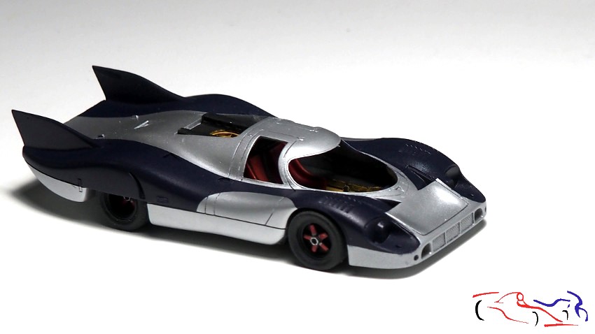
Y teniendo el chasis listo, y la carrocería pintada de aluminio, no pude resistirme a ponerlo todo junto, con las ruedas incluidas!!
And with the chassis ready, and the aluminum body painted, I couldn’t resist putting it all together, wheels included!
En este punto, quiero hacer mención a la parte trasera puesto que no me convencía. Le añadí una lámina de plástico, sobre la que irán las luces y las fijaciones del portón trasero:
At this point, I want to mention the rear section, as I wasn’t entirely satisfied with it. I added a plastic sheet, which will house the lights and the tailgate fixings.
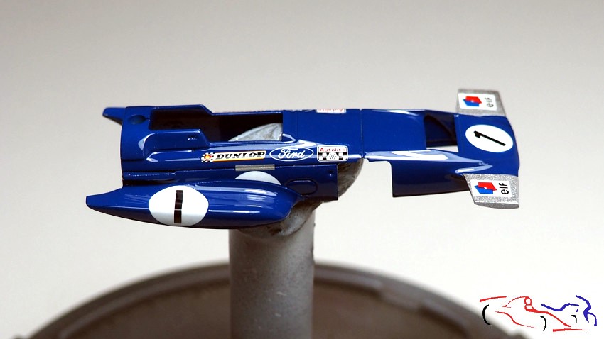
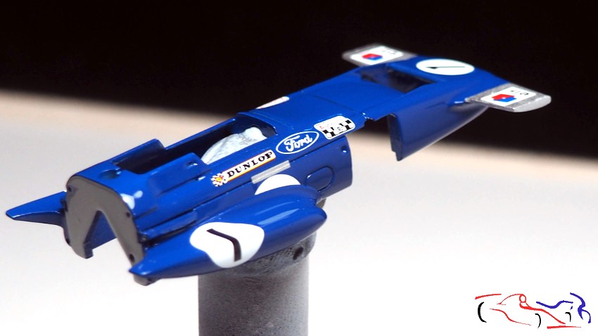
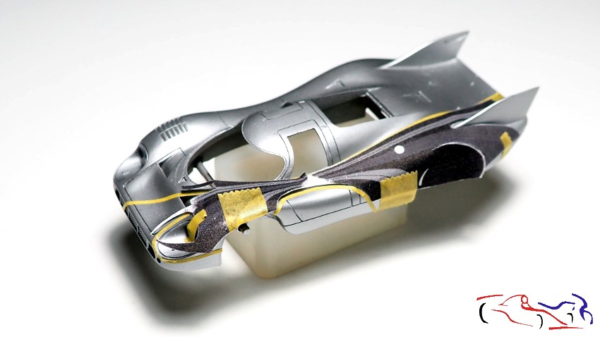
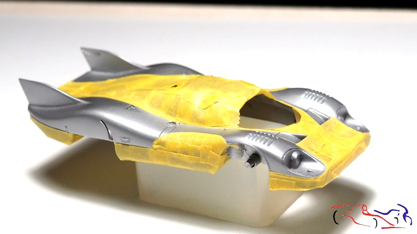
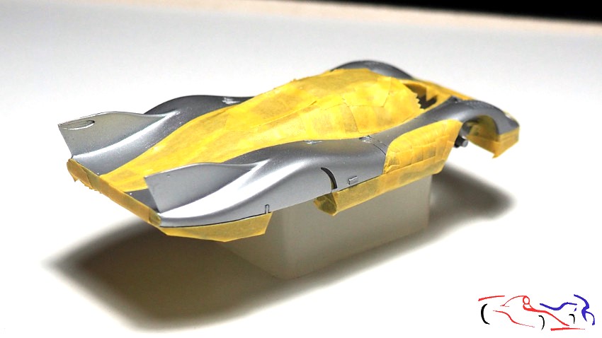
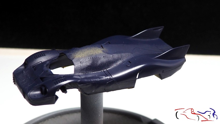
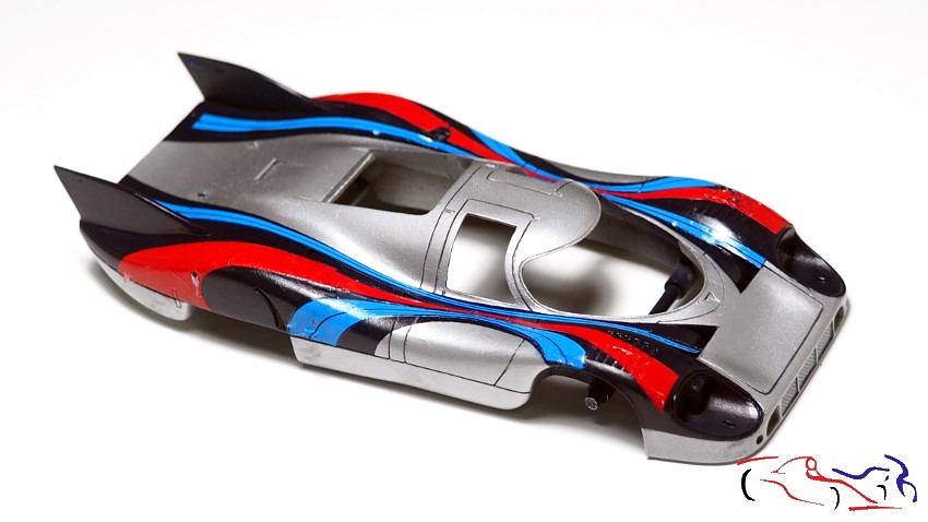
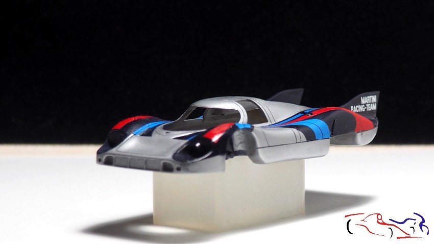
Y después de dar una capa de Future a pincel, empecé a poner las calcas y lo que había comentado en el primer post, se hizo realidad. Empecé por las calcas azules que recubren las dos derivas del alerón, pero las calcas estaban muy duras y al intentar doblarlas, se partían. Entonces decidí pintar al menos el azul oscuro. Para ello, saqué copias de las calcas, las recorté y las puse encima de la carrocería. Y con cinta de enmascarar muy fina, recorrí todo el contorno para delimitar el color azul. Hice los dos lados y tapé el resto:
And after applying a coat of Future paint with a brush, I started applying the decals, and what I mentioned in the first post came to fruition. I began with the blue decals covering the two winglets, but they were very stiff and broke when I tried to bend them. So I decided to at least paint the dark blue. To do this, I made copies of the decals, cut them out, and placed them on the bodywork. Then, using very thin masking tape, I went over the entire outline to define the blue area. I did both sides and masked off the rest.
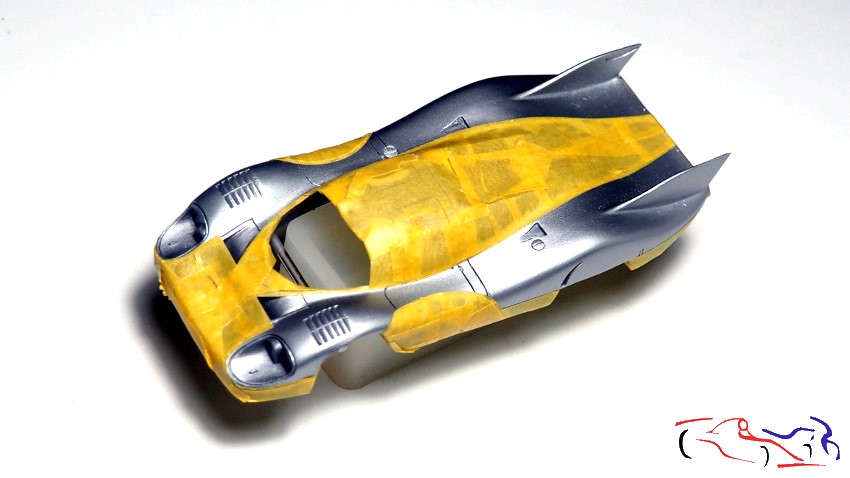
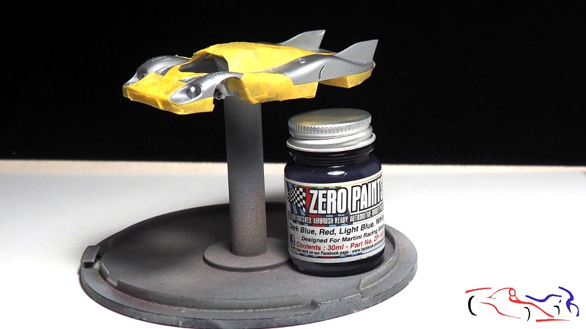
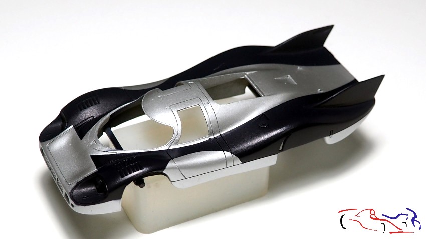
Y a continuación, pinté todo con el color específico de Zero Paint de Martini, que se parecía mucho y que tenía guardado.
And then I painted everything with the specific Martini Zero Paint color, which was very similar and which I had saved.
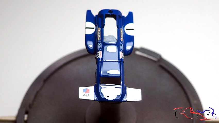
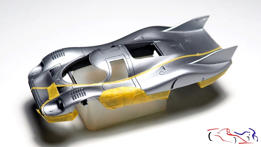
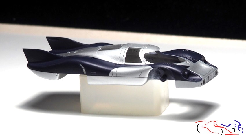
Y éste es el resultado al desenmascarar: sin ningún mayor problema! También le puse el chasis para ver como quedaba!! Y el resultado es bueno!!
And this is the result after unmasking: no problem at all! I also put the chassis on to see how it looked!! And the result is good!!
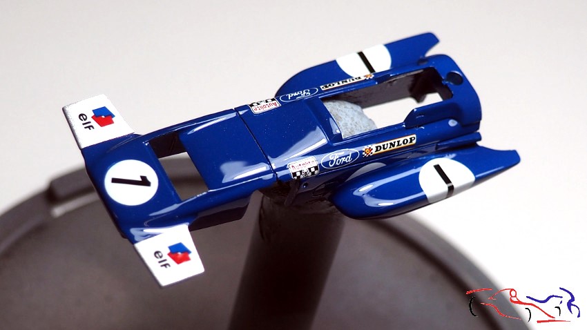
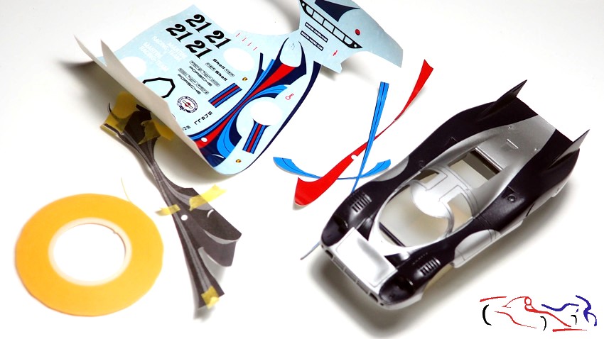
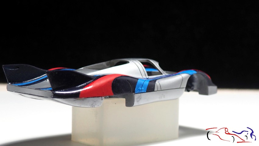
Una vez seco, me decidí a poner el resto de calcas previa capa de Micro Decal Film, para asegurarlas. Para ello, fui cortando como pude las bandas roja y azules con tijeras y cutter nuevo…
Once dry, I decided to apply the rest of the decals after first applying a layer of Micro Decal Film to secure them. To do this, I cut out the red and blue stripes as best I could with scissors and a new craft knife…
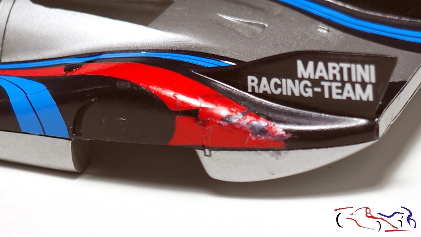
… pero fue una pesadilla!! A pesar del líquido protector, se rompían y al ser tan duras, no se doblaban, por mas que le daba los líquidos fuertes de calcas y el aire caliente. Además, no se pegaban ni de suerte, por lo que tenía que poner siempre el pegamento para calcas de Tamiya. Por tanto, decidí poner las planas con el líquido fuerte de Tamiya, y para las muy complicadas, usé el Strong de Tameo. Pero con este liquido, no hay que tocar la calca una vez puesta, y como se pegaban mal, hubo zonas desastrosas. Al final puse todas, lo que me llevó dos dias:
…but it was a nightmare!! Despite the protective liquid, they tore, and being so hard, they wouldn’t bend, no matter how much I used strong decal fluid and hot air. What’s more, they wouldn’t stick at all, so I always had to use Tamiya decal glue. Therefore, I decided to apply the flat decals with Tamiya’s strong fluid, and for the very intricate ones, I used Tameo’s Strong fluid. But with this fluid, you’re not supposed to touch the decal once it’s applied, and since they didn’t stick well, there were some disastrous areas. In the end, I applied them all, which took me two days.
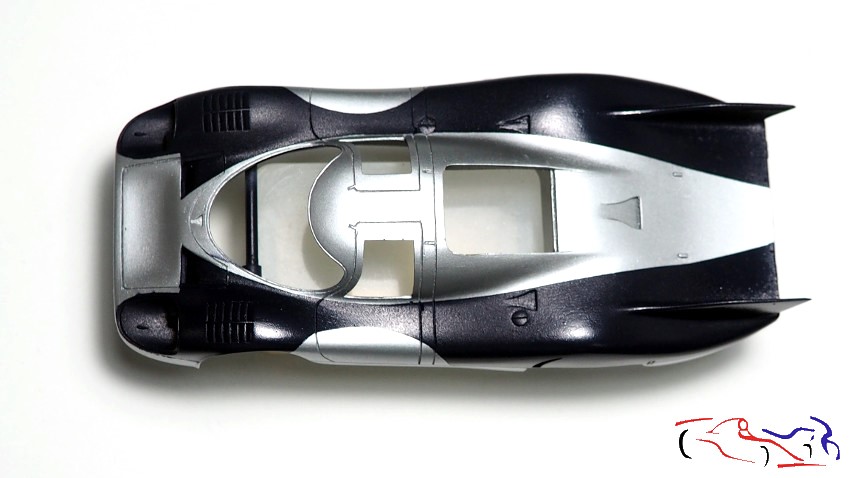
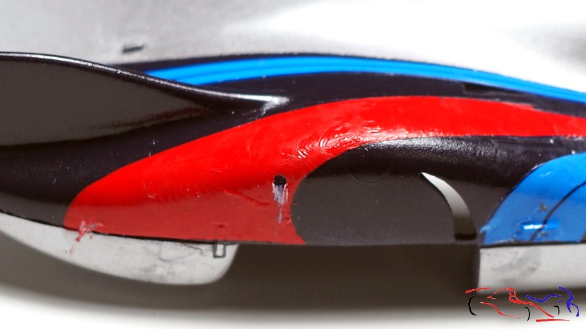
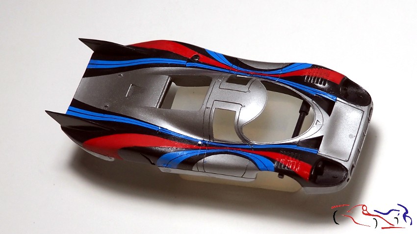
Si os fijáis bien, tuve muchos problemas, que paso a comentar (pulsad en la foto para ampliar):
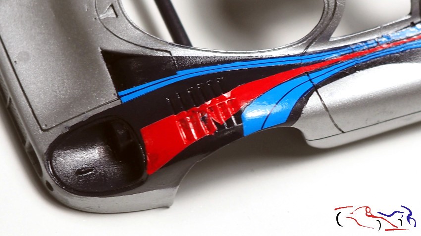
1-. La superposición de las calcas rotas, el líquido Strong de Tameo y la falta de exactitud de sus longitudes, hicieron este desastre.
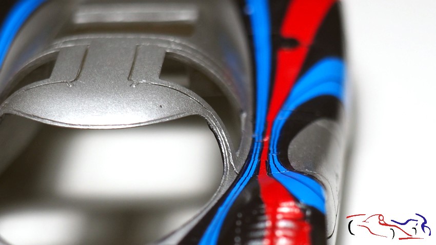
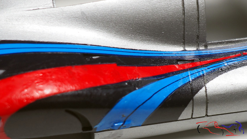
2-. La rotura de la calca azul interior en varios tramos hizo un rompecabezas para alinearlas.
3-. La falta de exactitud hizo que la calca no llegara a donde tenía que llegar.
4-. Mismo problema que la primera foto pero en el lado derecho.
5-. Tuve que cortar calcas para ajustarlas a la carrocería.
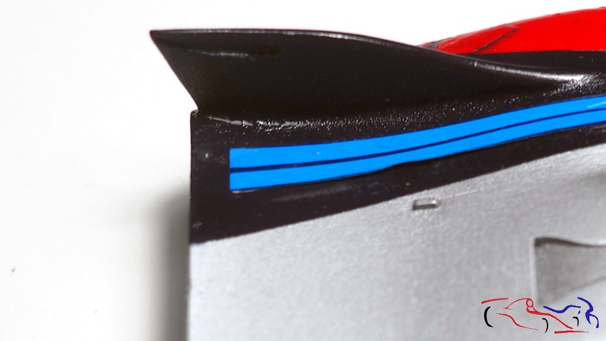
6-. Las calcas azules de este lado, no llegaban al final.
If you look closely, I had many problems, which I will now describe (click on the photo to enlarge):
1-. The overlapping of the torn decals, Tameo’s Strong liquid, and the inaccurate lengths caused this mess.
2-. The tearing of the inner blue decal in several sections made aligning them a real puzzle.
3-. The inaccuracy meant the decal didn’t reach where it was supposed to.
4-. Same problem as the first photo, but on the right side.
5-. I had to cut the decals to fit the body.
6-. The blue decals on this side didn’t reach the end.
1 23456
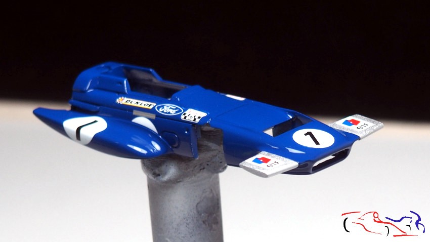
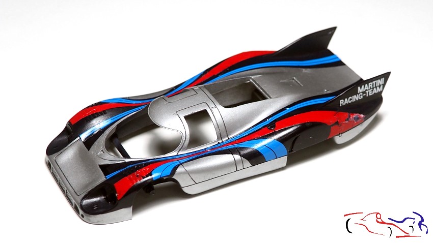
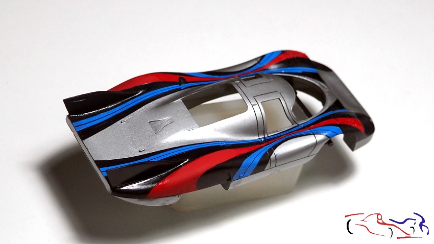
Total, que antes de continuar, me paré a pensar, qué hacía con ella. Pedí unas calcas extra a Lemans Decals, pero el azul oscuro no era correcto. Por tanto, mi decisión fue seguir hasta el final, intentando arreglar con pintura los errores y si quedaba mal, la ensuciaba como si fuese el final de las 24 horas. Al final, siempre se aprende algo!! Y me puse con ello: lijé con cuidado todo lo que estaba mal, pinté con el rojo de Vallejo, que era casi idéntico, todos los destrozos. Con el azul oscuro, de Zero, repinté lo que pude aun sabiendo que era pintura diluida para el aero. Y para el azul claro, cogí tres azules de Vallejo, y saqué el color, como se puede ver en las fotos donde aparecen las calcas que no llegaban al final:
So, before continuing, I stopped to think about what to do with it. I ordered some extra decals from Lemans Decals, but the dark blue wasn’t right. Therefore, my decision was to see it through to the end, trying to fix the mistakes with paint, and if it still looked bad, I’d just dirty it up as if it were the final 24-hour race. In the end, you always learn something! And I got to work: I carefully sanded everything that was wrong, painted over all the damage with Vallejo red, which was almost identical. With Zero dark blue, I repainted what I could, even knowing it was airbrush paint diluted. And for the light blue, I took three Vallejo blues and mixed the color, as you can see in the photos where the decals that didn’t quite reach the end are visible.
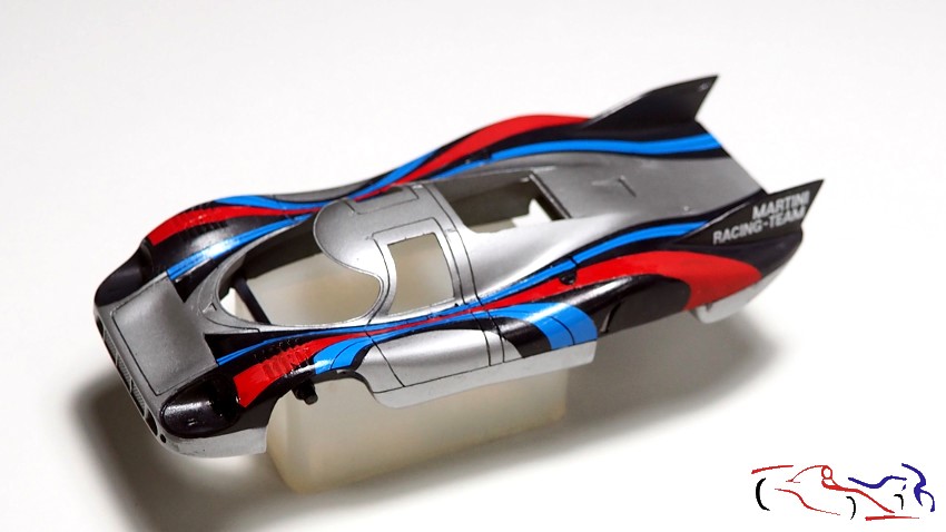
El resultado? Más que aceptable!!! Ahora a poner el resto de calcas y lacar, que os enseñaré en el siguiente post. Gracias por ver y comentar!!
The result? More than acceptable! Now to apply the rest of the decals and clear coat, which I’ll show you in the next post. Thanks for watching and commenting!
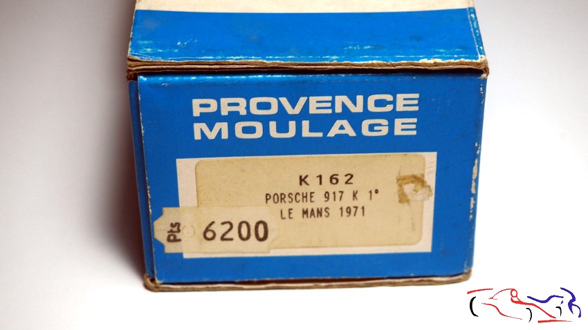
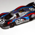
Hola a todos! Aunque hace muy poco he empezado otro proyecto, de un Porsche 917 que corrió e LeMans en 1971, hoy os muestro este kit, que también corrió en 1971, pero éste se llevó la victoria conducido por Helmut Marko y Gijs van Lennep. Mi idea es hacerlo casi al mismo tiempo, para que los dos se laquen al mismo tiempo, junto con el March 701, y asi, aprovechar ese proceso. El kit es otro Provence Moulage, que en su tiempo costó 6200 pesetas, que en euros sería 37,25 (no se cuando fue comprado en la tienda!!):
Hello everyone! Although I’ve only just started another project – a Porsche 917 that raced at Le Mans in 1971 – today I’m showing you this kit, which also raced in 1971, but this one took the win, driven by Helmut Marko and Gijs van Lennep. My plan is to build it at roughly the same time, so that both can be painted at the same time, along with the March 701, and thus make the most of that process. The kit is another Provence Moulage, which at the time cost 6,200 pesetas, which would be €37.25 (I don’t know when it was bought in the shop!!):
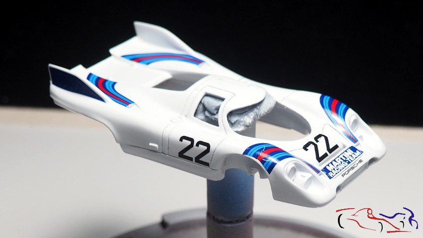
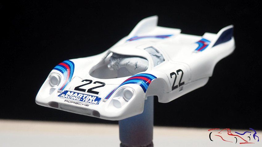
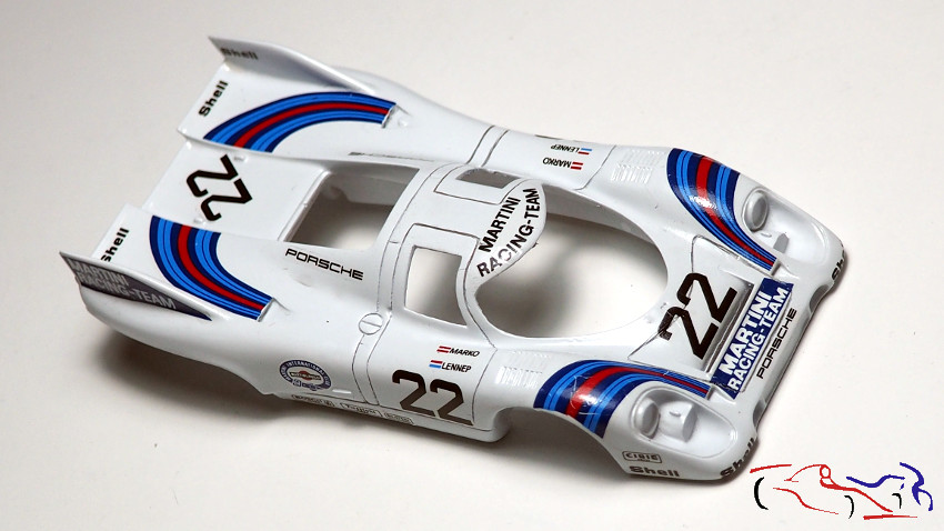
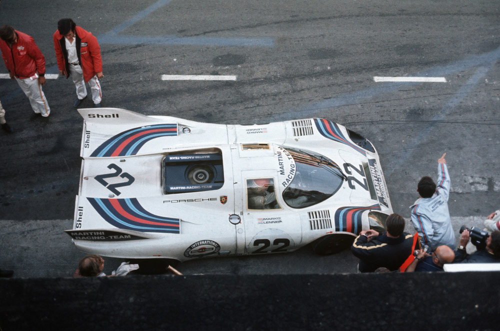
Y este es el modelo final:
And this is the final model:
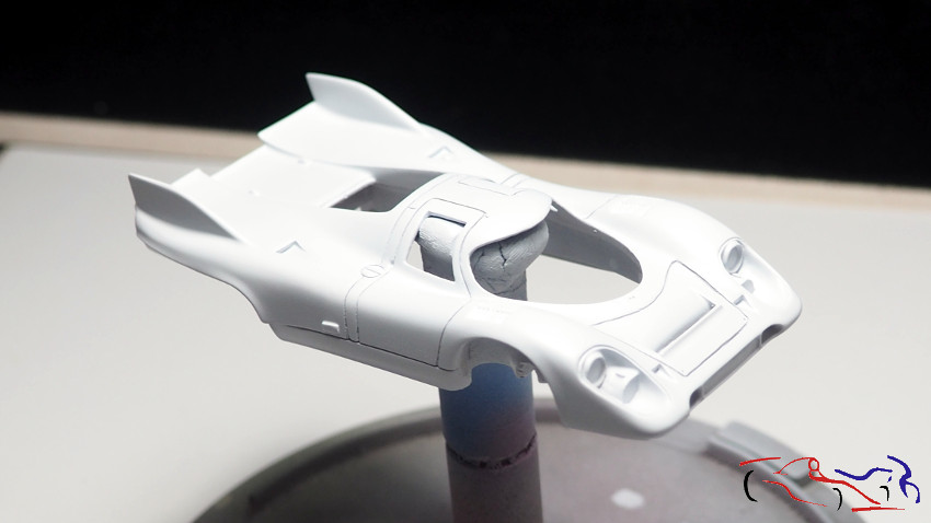
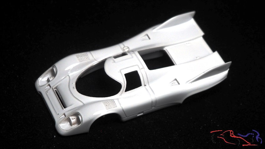
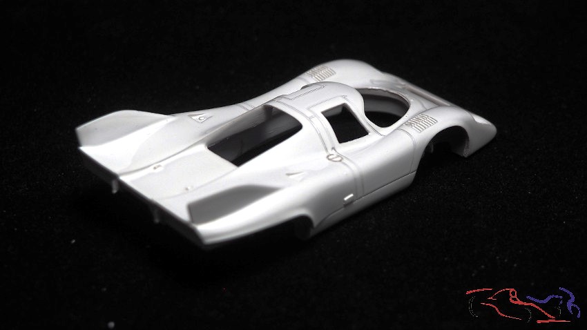
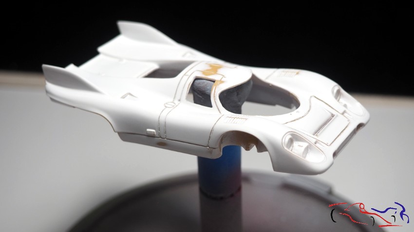
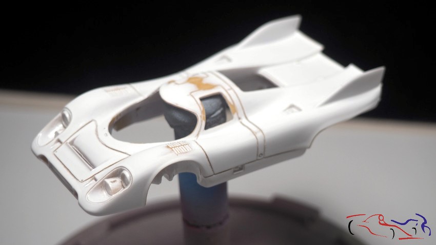
La carrocería es igualmente de resina, pero alguno de sus dueños anteriores, debió pintarlo de blanco, sin afinarla, ya que hay restos de rebabas, y sin profundizar las líneas de los paneles. Además, la capa de pintura fue generosa, por lo que muchas curvas eliminaron dichos paneles. Habrá que repasarla un poco!!
The bodywork is also made of resin, but one of its previous owners must have painted it white without sanding it down properly, as there are traces of rough edges, and without deepening the lines of the panels. What’s more, a thick layer of paint was applied, so many of the curves on those panels have been lost. It’ll need a bit of a touch-up!!
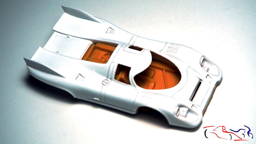
Aquí vemos la carrocería con su chasis:
Here we can see the bodywork with its chassis:
El chasis es muy similar al anterior kit, teniendo el salpicadero los embellecedores de las llantas y los alerones, común. De hecho, los alerones no nos servirán para este modelo.
The chassis is very similar to the previous kit, with the dashboard, wheel trims and spoilers being the same. In fact, the spoilers won’t be suitable for this model.
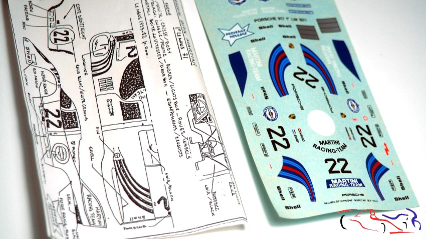
El resto de piezas es casi común, añadiendo un fotograbado para la estructura tubular trasera. En cuanto a las calcas, nada que decir de momento, y comentar, que este kit si trae una instrucciones…de pintura, posición de calcas y de la estructura trasera:
The rest of the parts are fairly standard, with the addition of a photo-etched part for the rear tubular frame. As for the decals, there’s nothing to report at the moment, and it’s worth noting that this kit does come with instructions… on painting, decal placement and the rear frame:
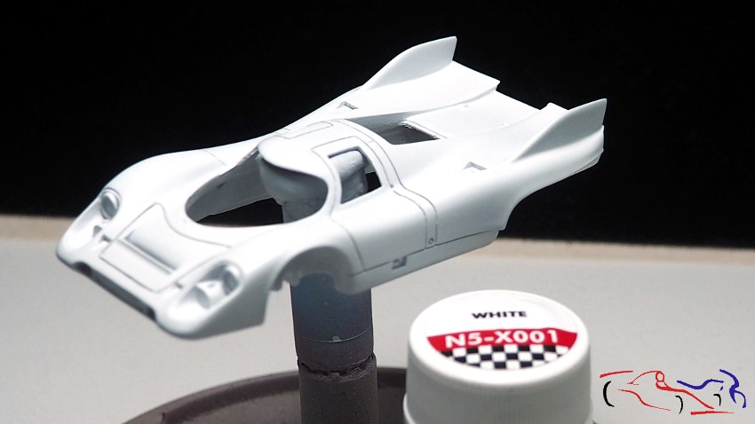
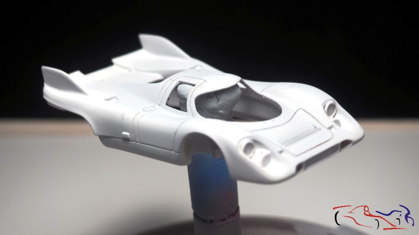
Lo primero que he hecho es profundizar los paneles, y lijar toda la pintura para que la imprimación agarre:
The first thing I did was to deepen the panels and sand off all the paint so that the primer would adhere properly:
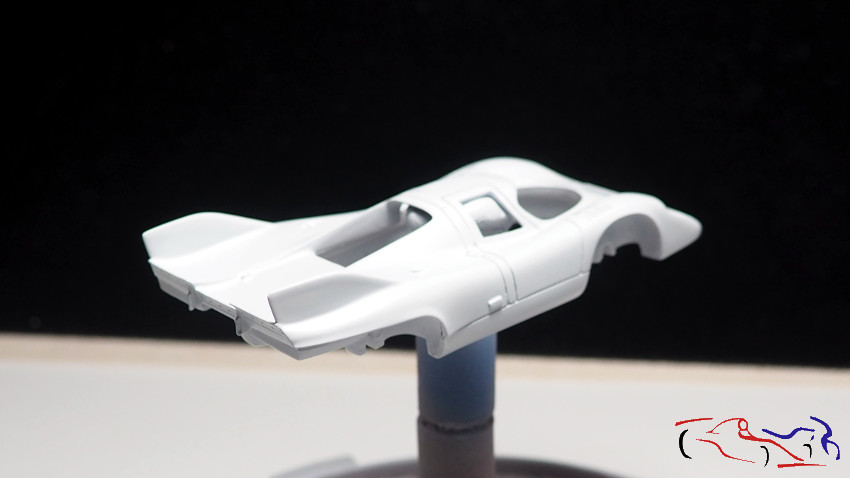
Una vez hecho, imprimo la carrocería y el resto de piezas con Gravity:
Once that’s done, I print the body and the rest of the parts using Gravity:
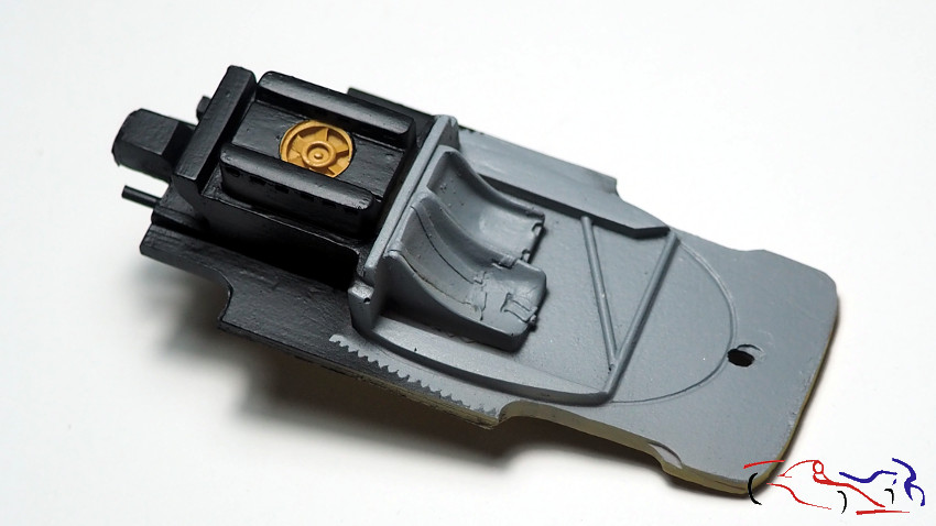
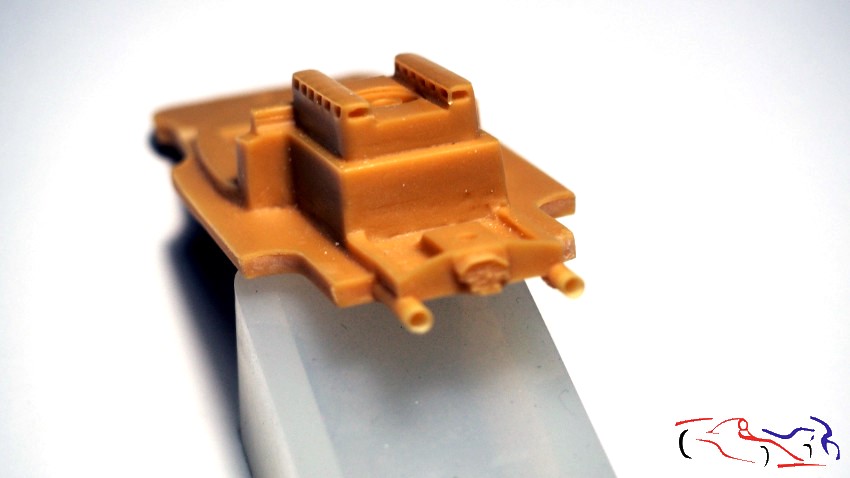
En cuanto al chasis, veo que la parte trasera deja mucho que desear y decido arreglarla. Lo primero, substituyo los escapes por unos de latón, a los cuales, adelgazo el espesor y les añado una fijación con plástico. En la foto, podéis ver un escape terminado con su fijación, y el otro, el de abajo, sin terminar:
As for the chassis, I can see that the rear end leaves a lot to be desired, so I’ve decided to fix it. First of all, I’m replacing the exhaust pipes with brass ones, which I’m thinning down and fitting with plastic mounts. In the photo, you can see one exhaust pipe with its mount already fitted, and the other one, at the bottom, still unfinished:
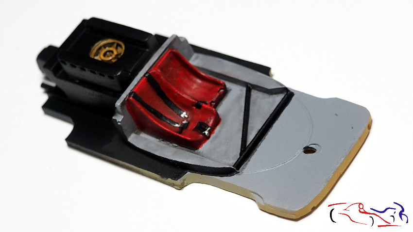
Y una vez imprimados, pinto de negro semi mate LP de tamiya las llantas, salpicadero, embellecedores de las llantas, y un fotograbado donde irán las luces traseras, y con Aluminium de la gama Metal de Zero Paints, los escapes y lo que serán los interruptores del salpicadero:
And once primed, I paint the wheels, dashboard, wheel trims and a photo-etched part where the rear lights will go with Tamiya LP semi-matt black, and the exhausts and what will become the dashboard switches with Aluminium from the Zero Paints Metal range:
Esto es todo de momento!! Gracias por ver y comentar!!
That’s all for now!! Thanks for watching and commenting!!
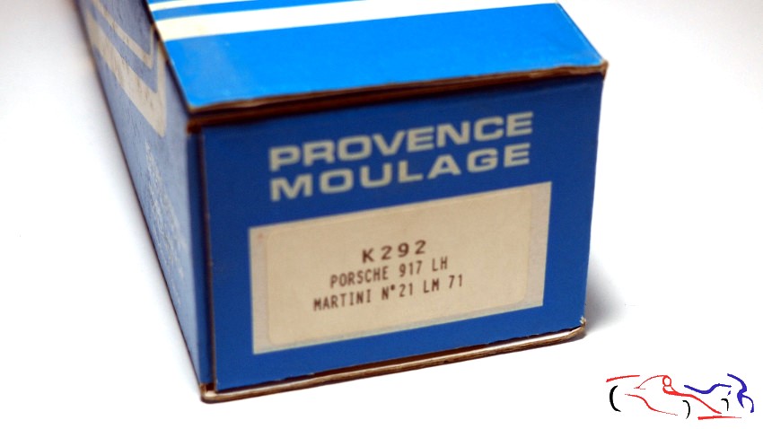
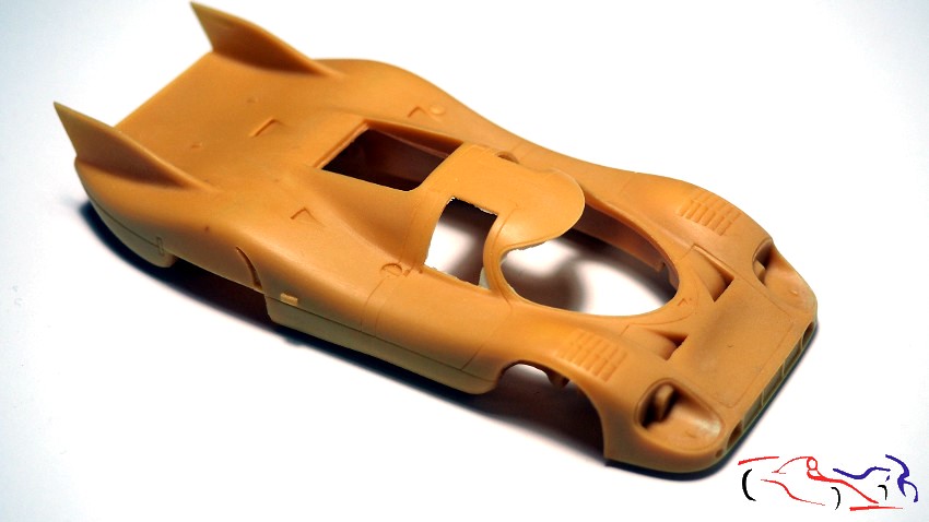
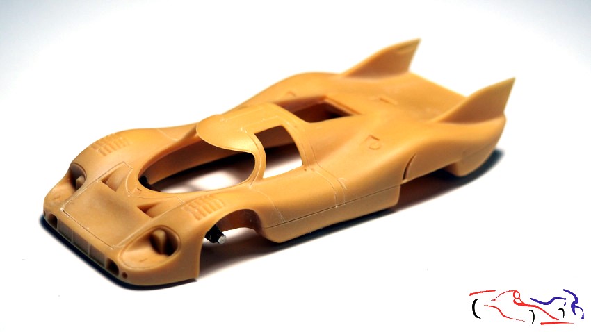
Hola a todos!! He pensado que podía hacer más kits a 1/43, para aprovechar el proceso del lacado, y viendo los coches que tengo pendientes, he escogido dos de la marca Provence Moulage, con poco despiece, y que con un poco de esfuerzo, pueden salir unos buenos proyectos. El primero es éste: Porsche 917 LH (Long Tail = Cola Larga) que corrió en 1971, con los colores de Martini.
Hello everyone! I thought I could make more 1/43 scale kits to take advantage of the painting process, and looking at the cars I have pending, I’ve chosen two from Provence Moulage, which have few parts and, with a little effort, could turn into some great projects. The first is this one: a Porsche 917 LH (Long Tail) that raced in 1971, in Martini livery.
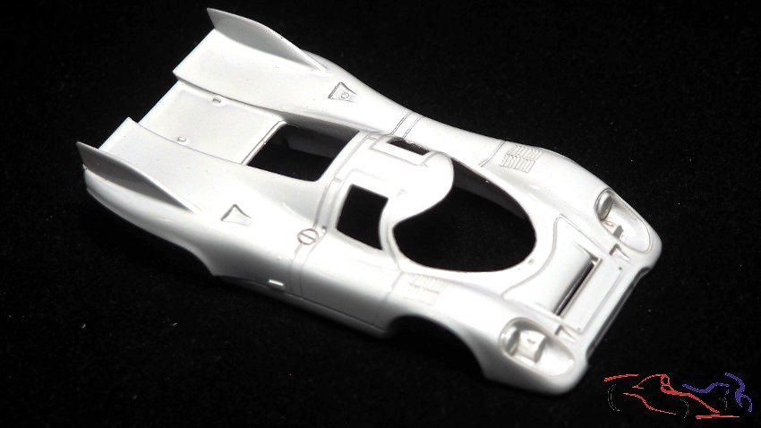
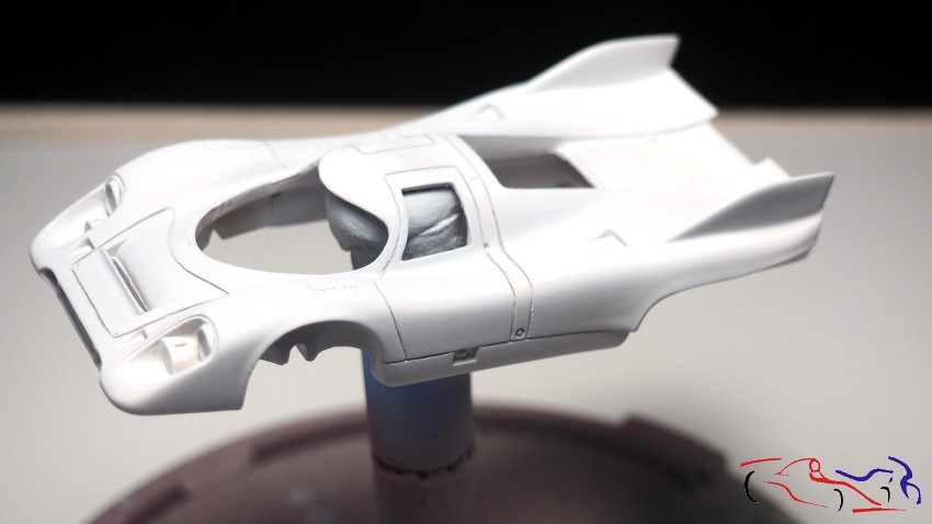
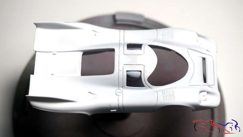
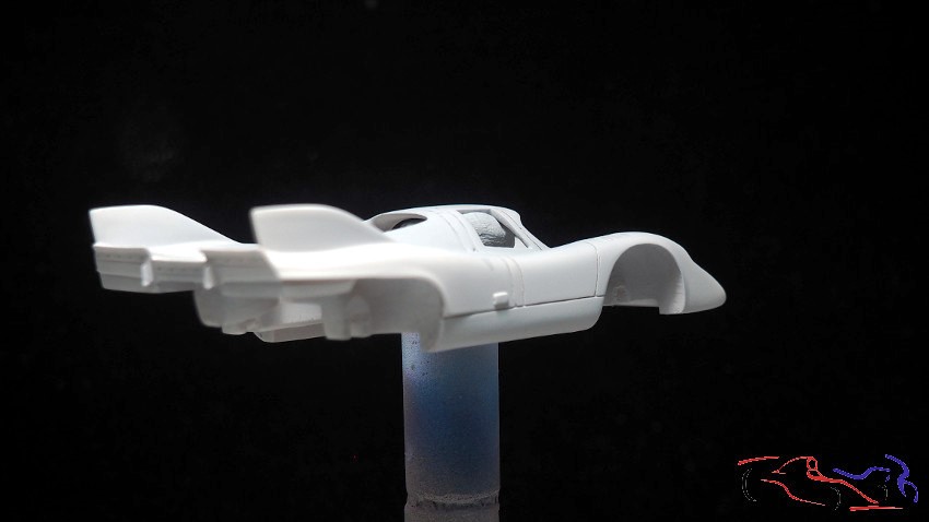
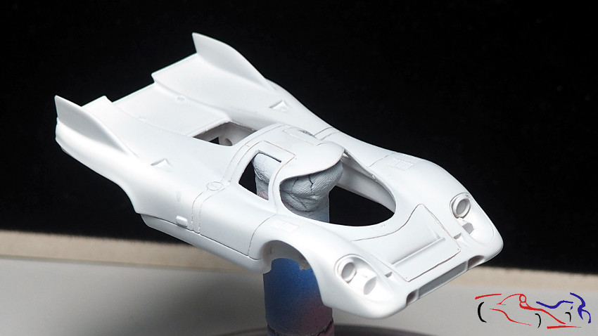
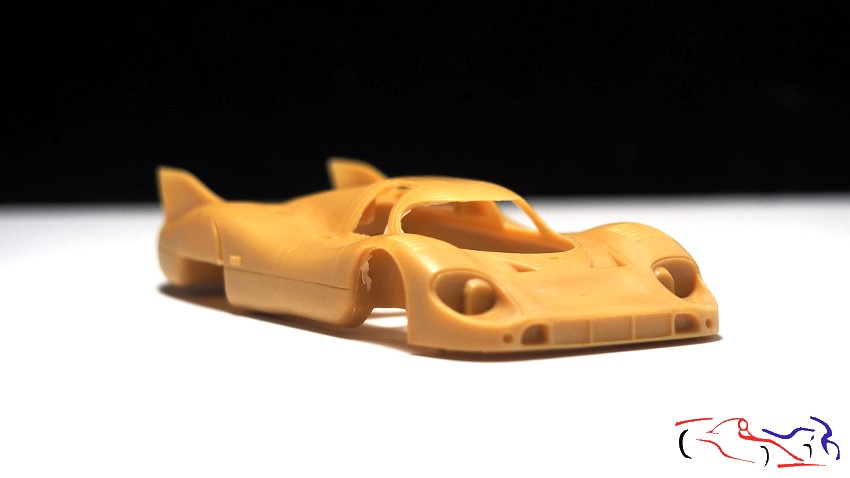
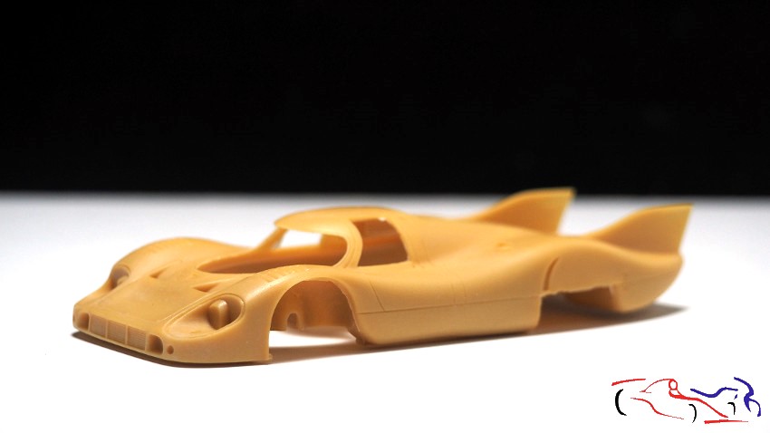
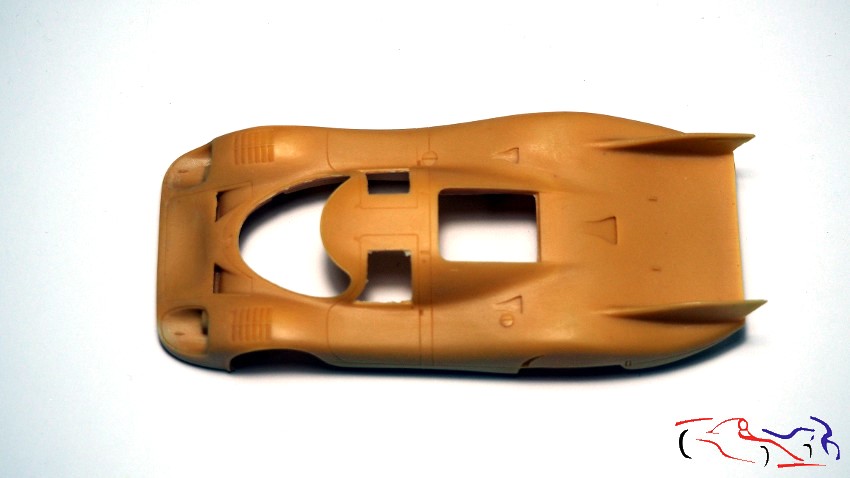
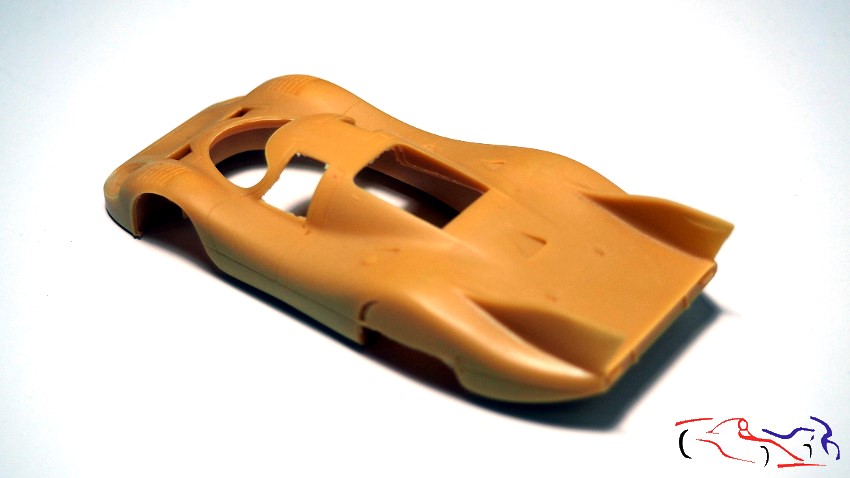
La carrocería es de resina, que si bien tiene buenas formas, hay que limpiarla de rebabas, y profundizar el panelado:
The body is made of resin, which, although it has good shapes, needs to be cleaned of burrs, and the paneling needs to be deepened:
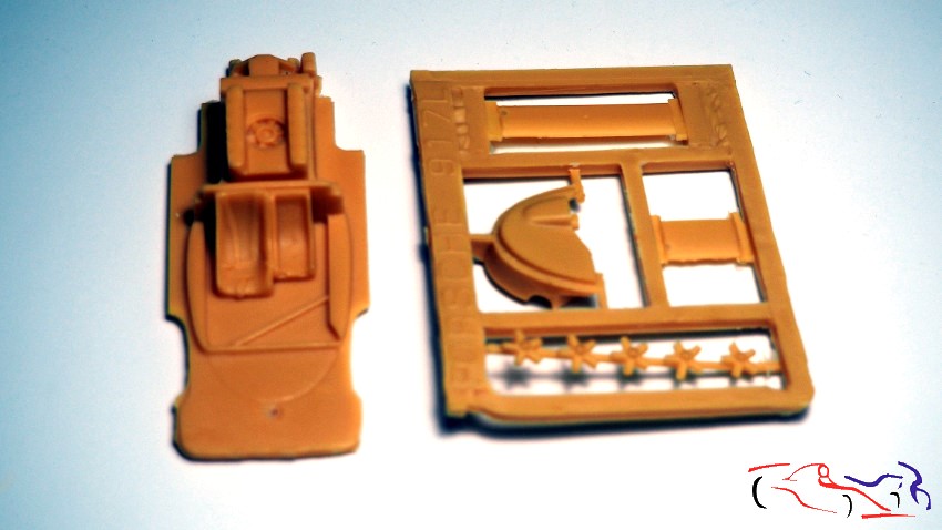
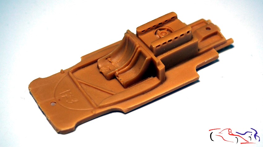
El chasis es también de resina, y vienen incluidos los asientos y el motor:
The chassis is also made of resin, and the seats and motor are included:
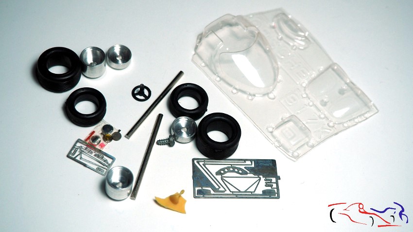
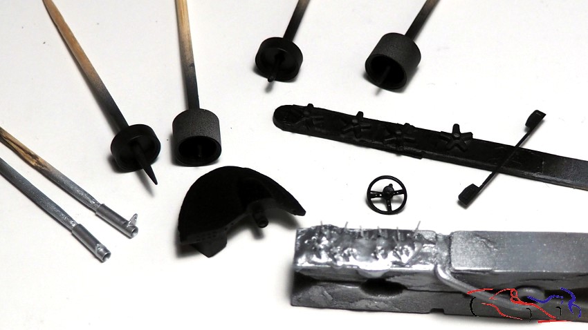
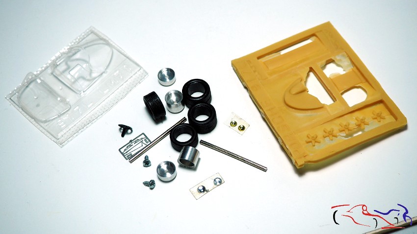
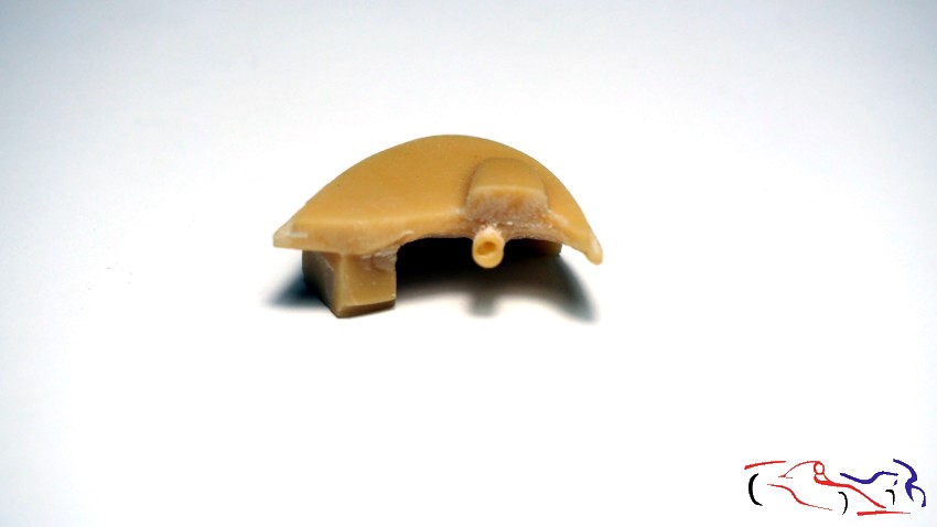
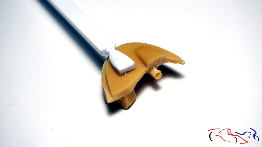
El resto de piezas las veis a continuación, en resina, metal, fotograbados y un vacuoformado para los cristales. Podréis comprobar, que el salpicadero, alerón trasero y las llantas están dentro de esa resina, que habrá que trabajar:
The remaining parts are shown below, made of resin, metal, photo-etched parts, and vacuum-formed glass. You’ll notice that the dashboard, rear spoiler, and wheels are embedded in the resin, which will require further work.
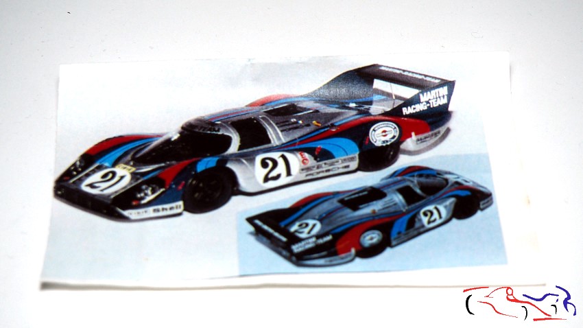
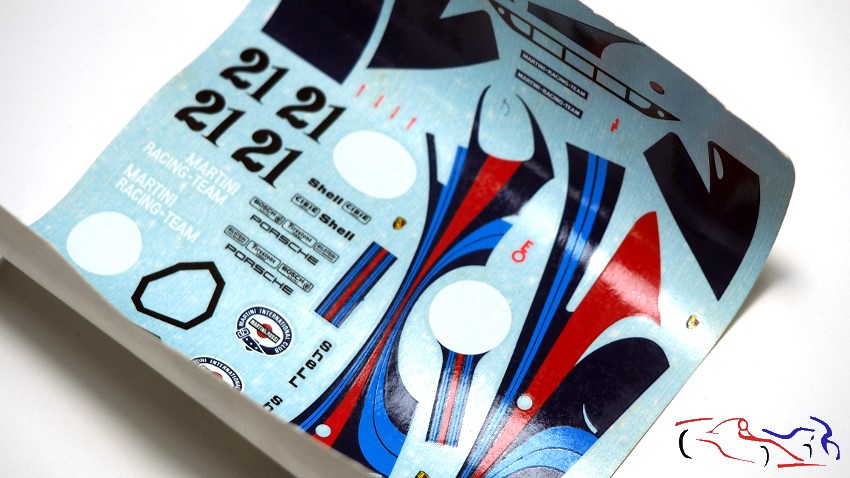
Las calcas son de Cartograph, pero al ser un kit muy antiguo, pueden dar problemas:
The decals are from Cartograph, but since it’s a very old kit, they may cause problems:
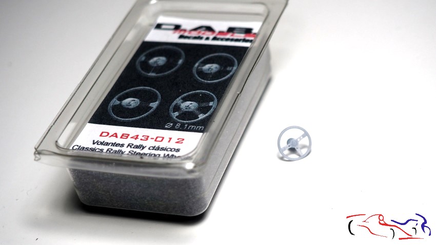
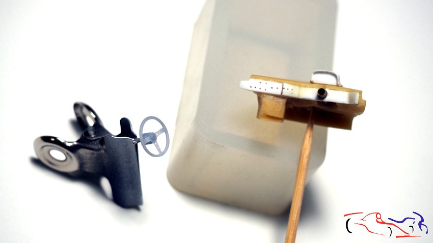
Una de las cosas que de momento le voy a poner es un volante de DAB Models, ya que el original deja mucho que desear:
One of the things I’m going to add for now is a DAB Models steering wheel, since the original leaves a lot to be desired:
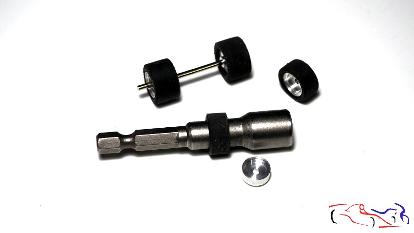
Y empezamos con el proceso: primero torneamos las ruedas para gastarlas y reducir un poco el diámetro. Lo hago lijándolas en ese útil del taladro:
And we begin the process: first we turn the wheels to wear them down and reduce the diameter a little. I do this by sanding them on that attachment of the drill:
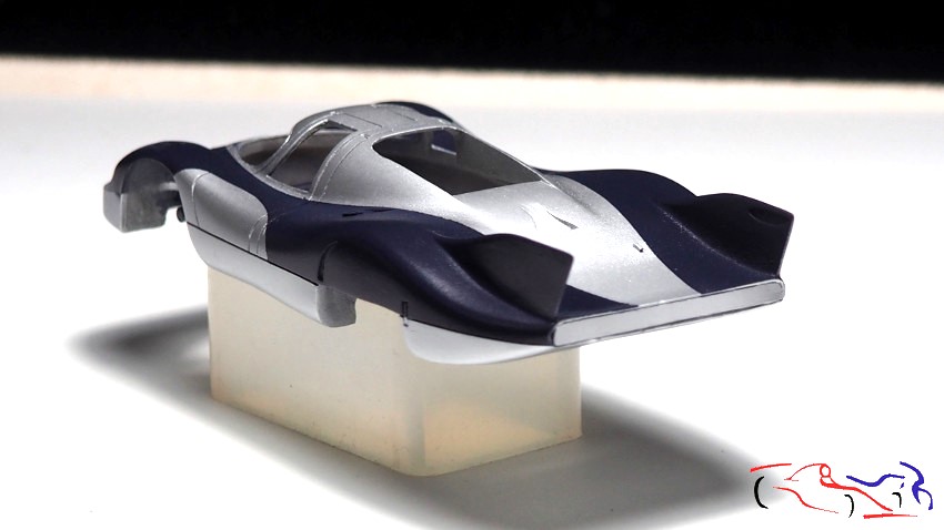
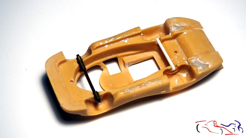
En cuanto a la carrocería, relleno burbujas por la parte inferior, y le ajusto los ejes de las ruedas, añadiendo unos tubos en las de delante, y una base en la trasera, para levantar la carrocería. Los ejes están acortados porque sobresalían de las llantas:
As for the body, I filled in any air bubbles underneath and adjusted the wheel axles, adding tubes to the front wheels and a base to the rear to raise the body. The axles were shortened because they were sticking out beyond the rims.
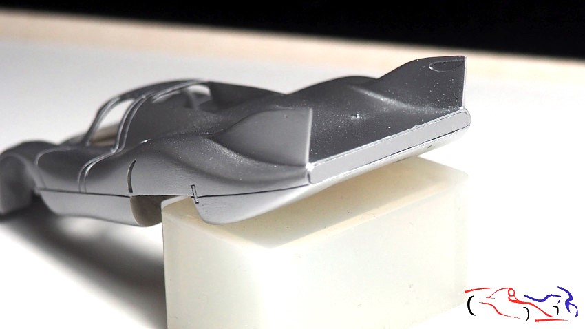
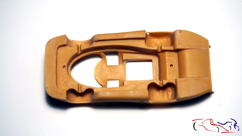
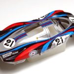
Aquí os presento la carrocería, una vez eliminadas las rebabas, profundizadas las líneas, y con una lijada completa a toda la superficie:
Here I present the bodywork, once the burrs have been removed, the lines deepened, and the entire surface has been completely sanded:
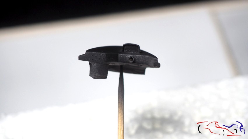
Pasamos al salpicadero. Podéis comprobar que es lo menos parecido a un salpicadero: la caja de relojes, que no tiene profundidad, no cuadra con la barra de la dirección, rebabas por todos lados…. Lo primero es hacer una caja de relojes, puesto que la original hay que eliminarla, y ponerle profundidad. La hago tallando una barra de plástico. Le rebajo todo el frontal para poner unas tiras de plástico donde le hago los agujeros de los interruptores, y le remplazo la guía de la dirección:
Let’s move on to the dashboard. You can see it’s the least like a dashboard: the instrument cluster, which has no depth, doesn’t align with the steering column, and there are burrs everywhere… The first thing is to make a new instrument cluster, since the original one has to be removed, and give it depth. I make it by carving a plastic rod. I reduce the entire front edge to attach some plastic strips where I drill the holes for the switches, and I replace the steering column guide.
Y todo listo para imprimar y pintar:
And everything is ready for priming and painting:
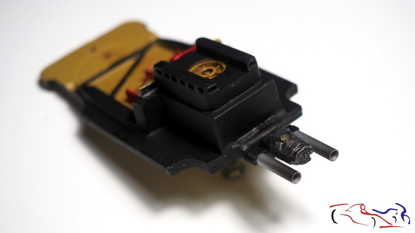
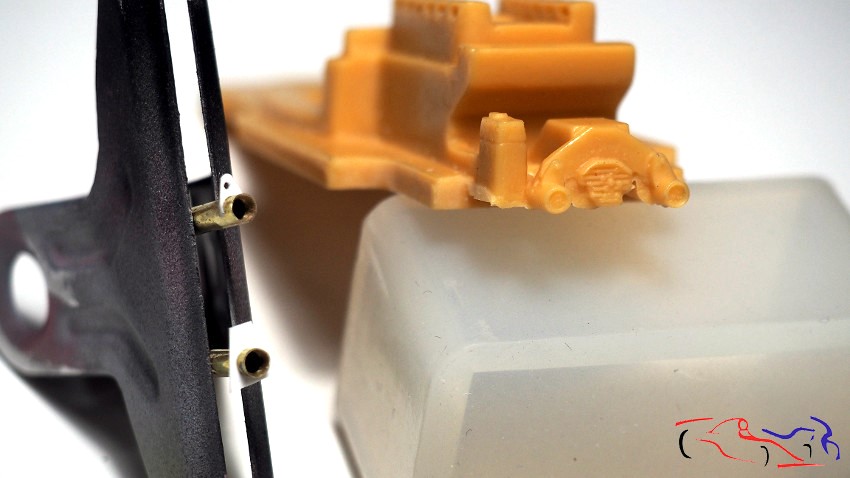
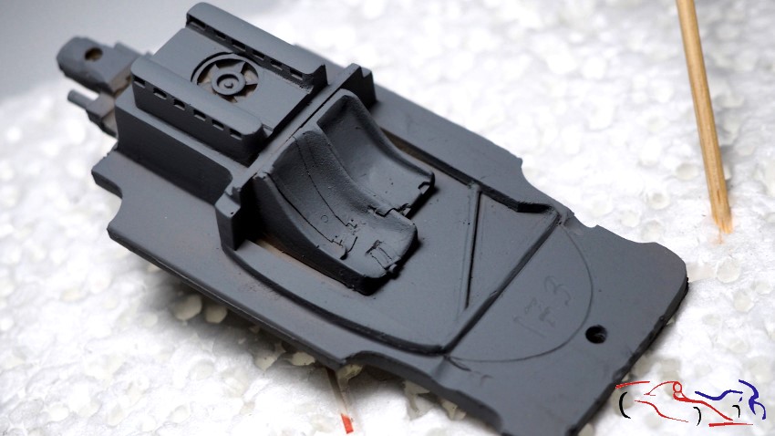
Si nos movemos al chasis, decir que los escapes están muy separados de la caja de cambios (los remplazaré por unos tubitos de metal), y eliminaré todo menos la caja de cambios. En la foto del chasis imprimada (con imprimación gris oscura de Gravity), se ve un poco la parte trasera que he modificado, y que más adelante mostraré:
Moving on to the chassis, the exhaust pipes are quite far from the gearbox (I’ll replace them with small metal tubes), and I’ll remove everything except the gearbox. In the photo of the primed chassis (with Gravity dark gray primer), you can see a bit of the rear section I’ve modified, which I’ll show later.
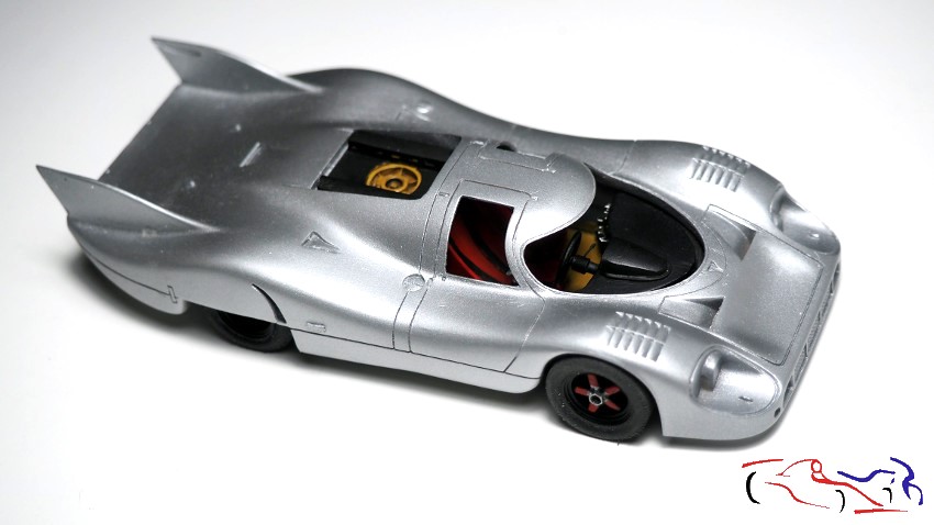
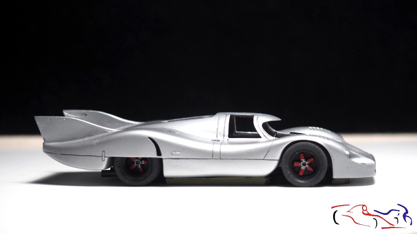
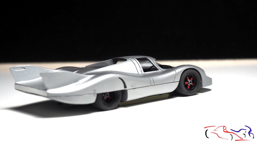
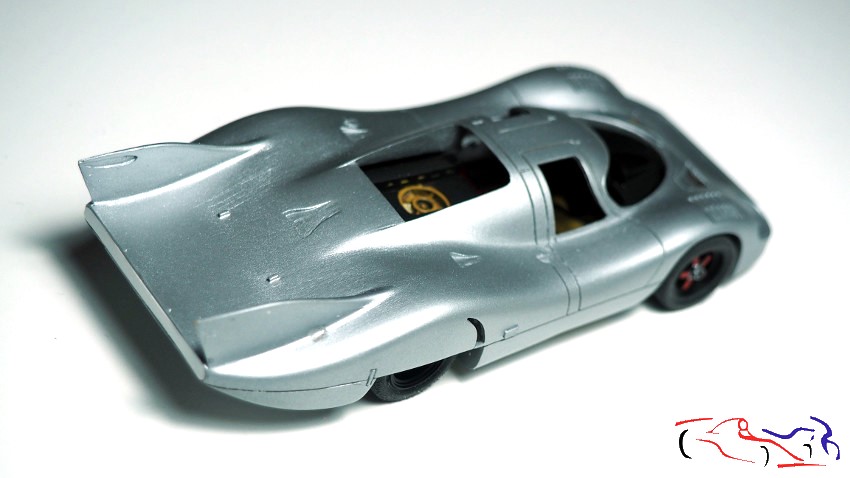
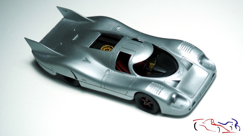
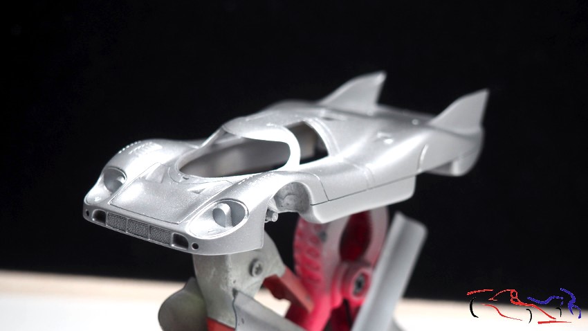
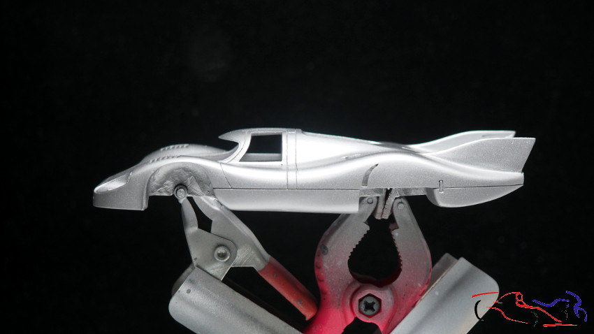
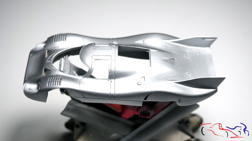
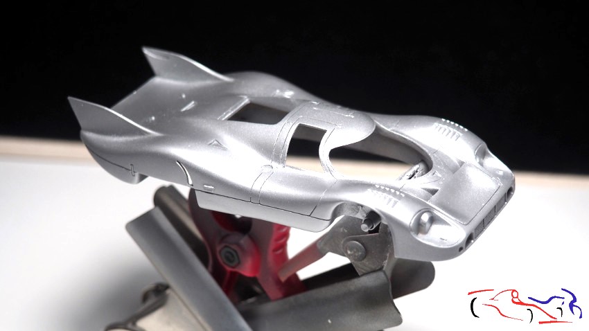
Una vez imprimada la carrocería con el gris oscuro de Gravity, le aplico el Alcoa Aluminium de la misma marca. Resultado: muy fino y muy fácil de aplicar:
Once the car body was primed with Gravity’s dark gray, I applied the Alcoa Aluminium from the same brand. Result: very smooth and very easy to apply.
Esto es todo de momento. Gracias por ver y comentar!!
That’s all for now. Thanks for watching and commenting!