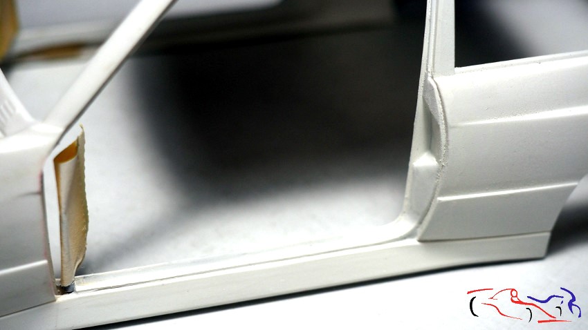
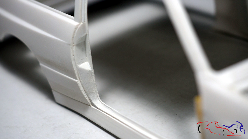
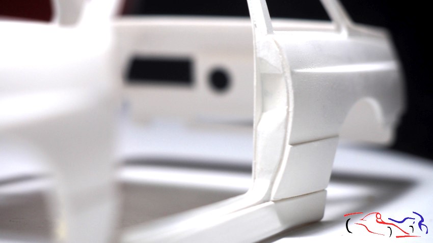
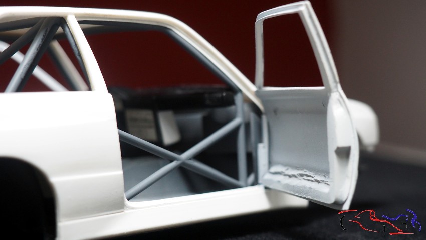
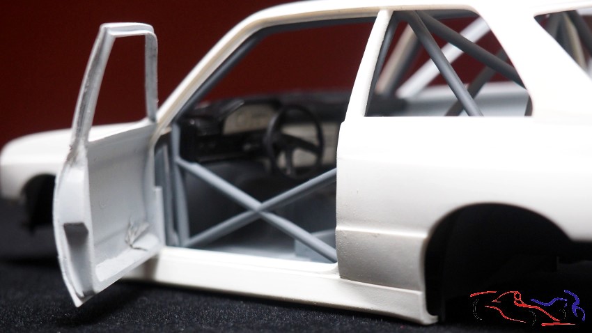
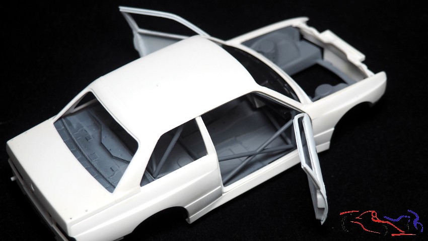
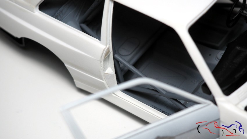
Hola a todos. Después de mucho tiempo sin subir actualizaciones, hoy toca actualizar este proyecto, con todo lo que he ido haciendo. Y para empezar, unas vistas de los encajes de las puertas tanto en la carrocería como en las propias puertas. En las fotos siguientes, podéis ver lo que se ha modificado para que encajen tal y como ocurre en el modelo real, incluyendo la muesca en la puerta donde se introduce el cierre:
Hello everyone. After a long time without posting updates, today I’m updating this project with everything I’ve been working on. To start, here are some views of the door fits, both on the body and on the doors themselves. In the following photos, you can see what has been modified to make them fit just like on the real model, including the notch in the door where the latch is inserted:
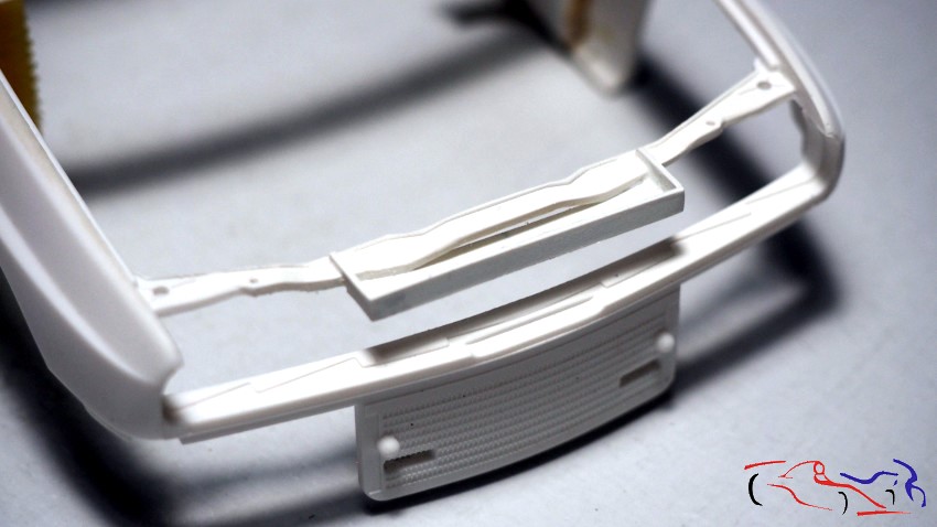
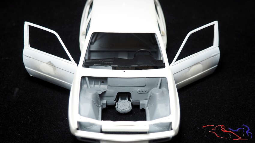
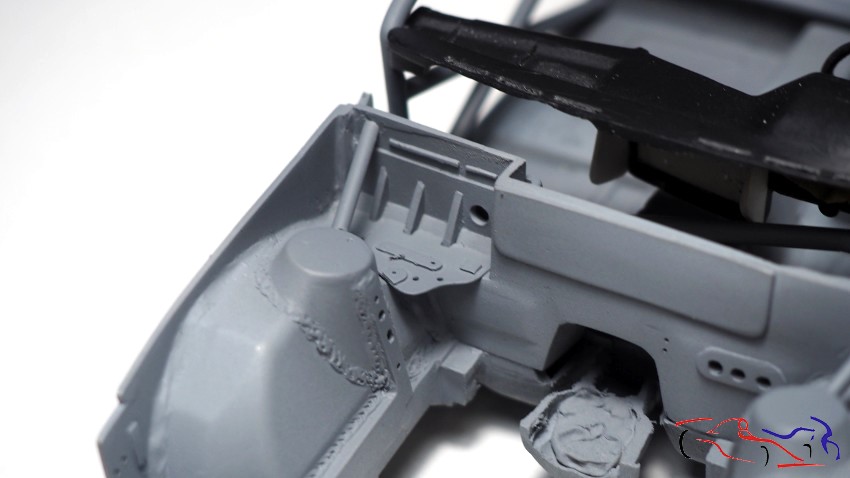
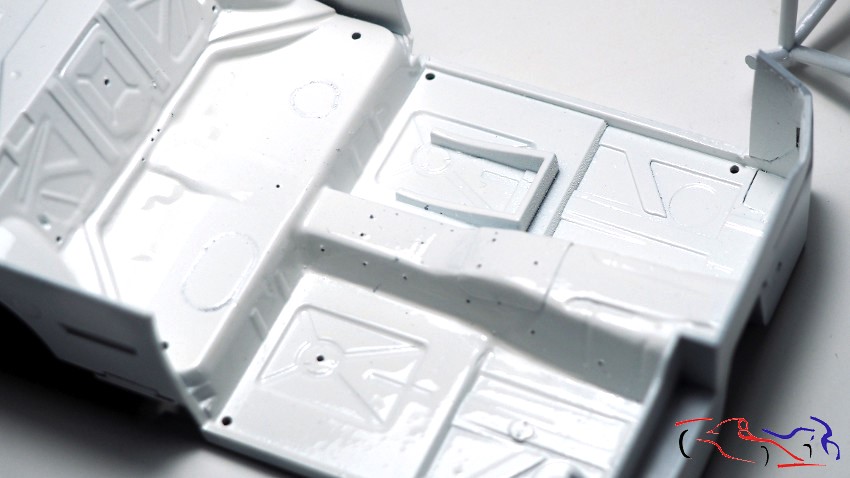
A continuación, os muestro la bandeja donde irá la bisagra del capó:
Next, I’ll show you the tray where the hood hinge will go:
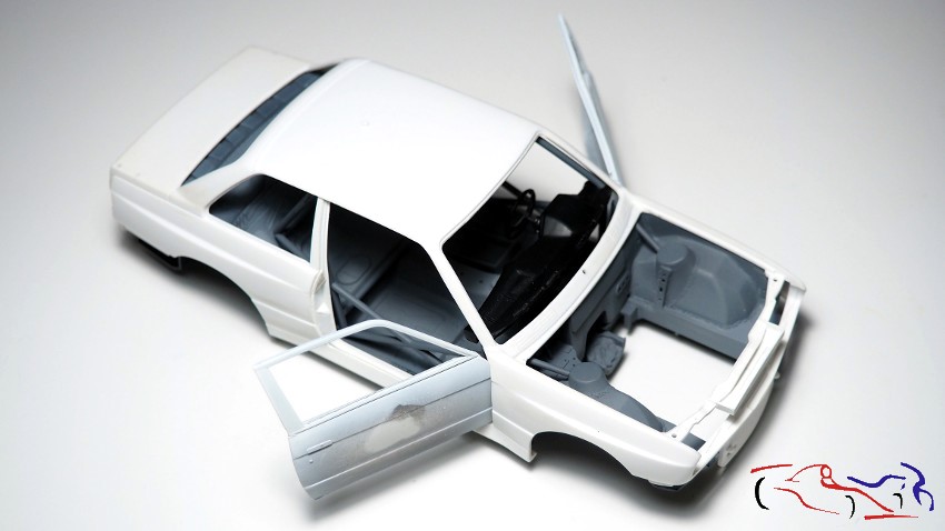
Y si montamos todo para ver encajes, tenemos el conjunto de la carrocería con las puertas abiertas:
And if we assemble everything to check the fit, we have the complete body with the doors open:
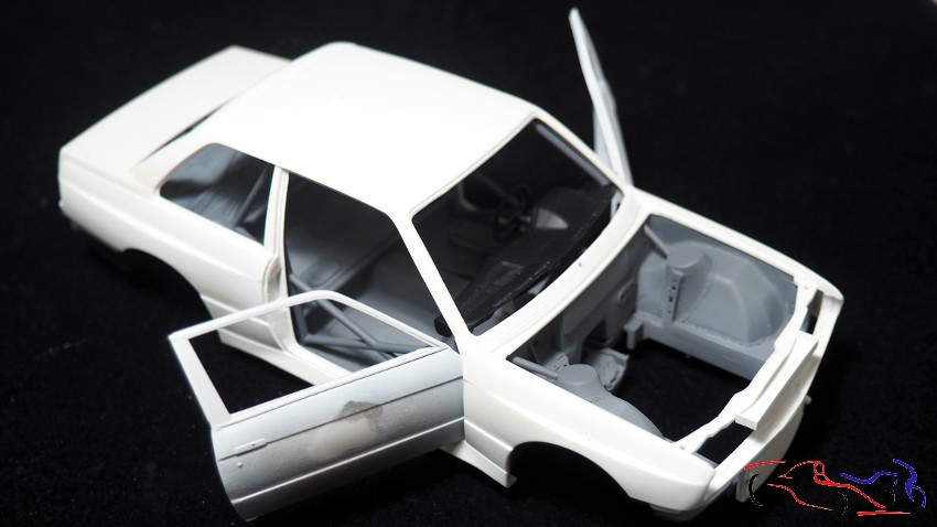
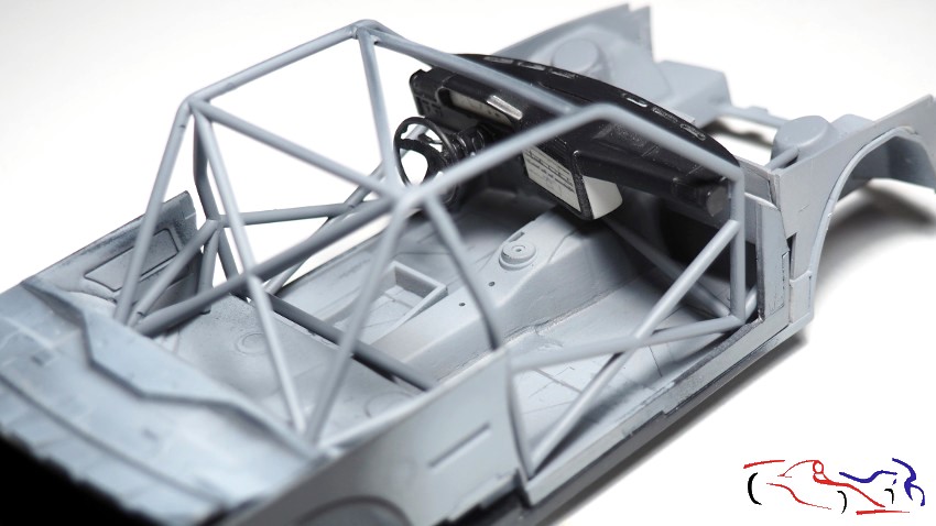
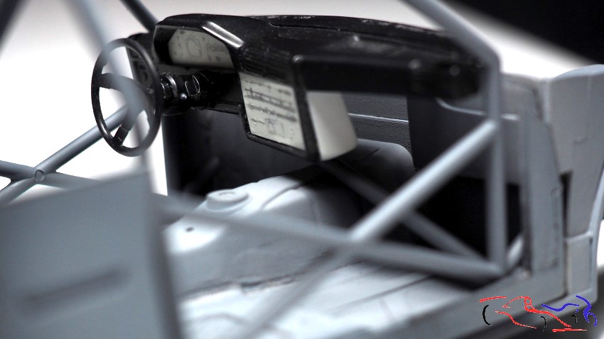
A continuación, tres fotografías del chasis con el cockpit, el arco de seguridad y el salpicadero colocados:
Below are three photographs of the chassis with the cockpit, roll cage, and dashboard in place:
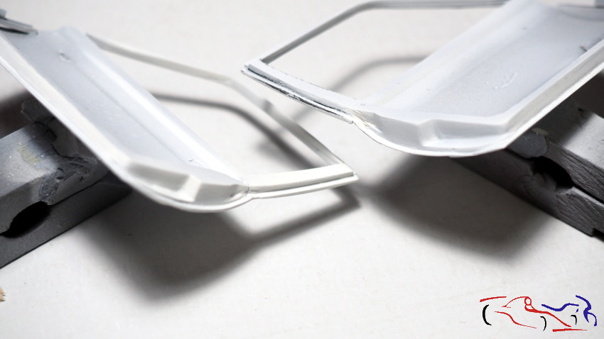
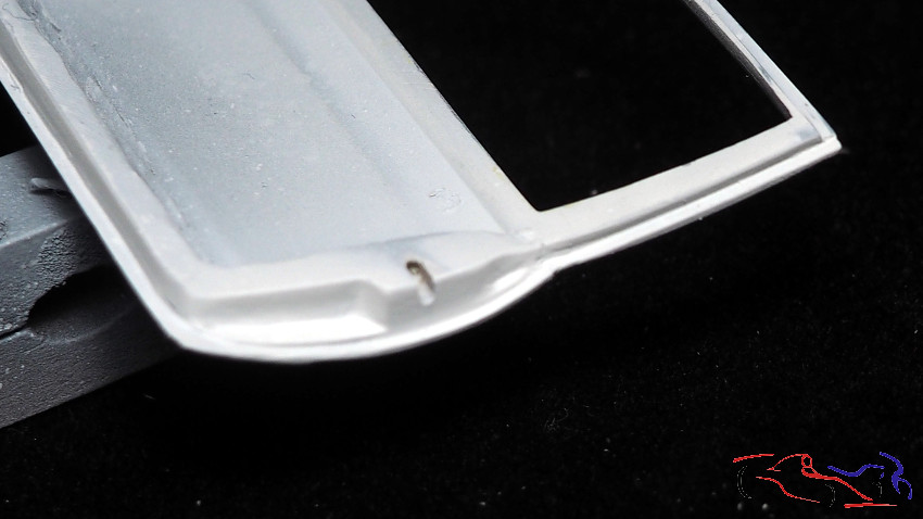
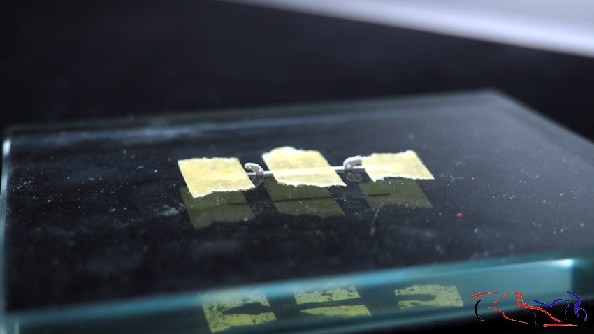
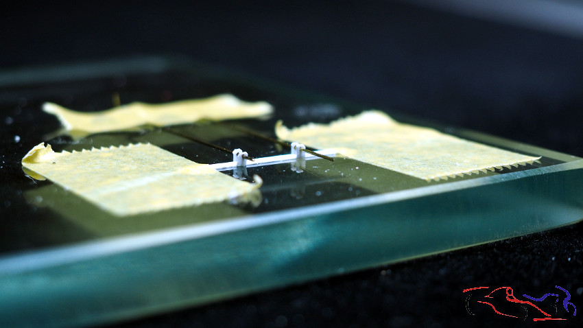
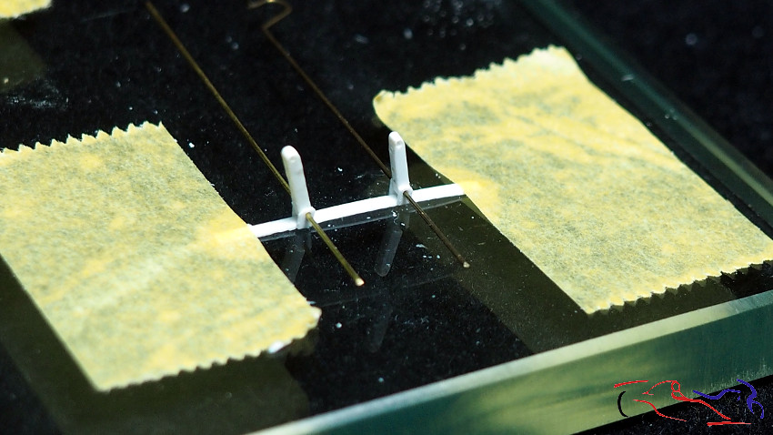
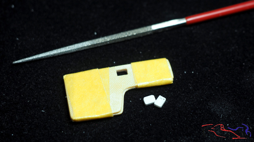
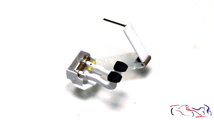
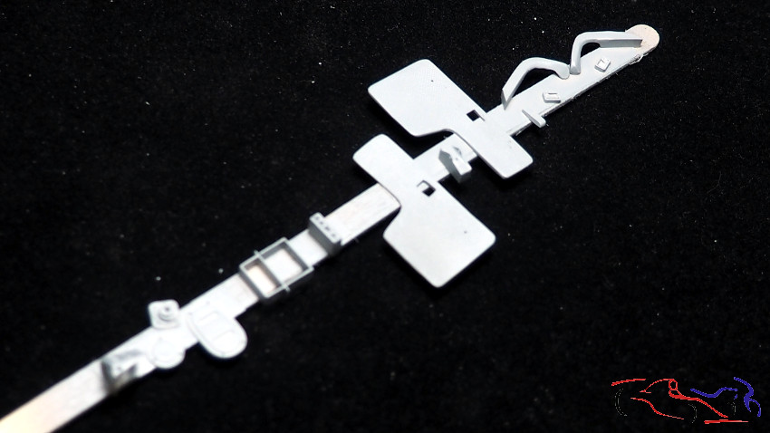
Y después de mostrar como va el conjunto, pasamos a las piezas nuevas que he realizado. Empezamos con los cierres y bisagras del capó. La primera foto, os muestro las fijaciones del capó, que van situadas en la parte más cercana al cristal. Están realizadas con plasticar con sus respectivos agujeros. En las dos siguientes fotos, vemos las piezas que irán en el capó, en la parte delantera, y donde se abatirá para abrirse. Los extremos de los palitos verticales irán colocados en la parte del chasis, en la bandeja que he mostrado anteriormente.
And after showing how the assembly is coming together, we move on to the new parts I’ve made. We’ll start with the hood latches and hinges. In the first photo, I’m showing you the hood fasteners, which are located on the side closest to the windshield. They’re made of plasticine with their respective holes. In the next two photos, you can see the pieces that will go on the front of the hood, where it will fold down to open. The ends of the vertical rods will be attached to the chassis, on the tray I showed earlier.
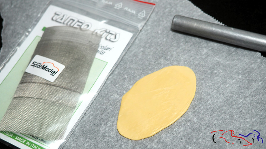
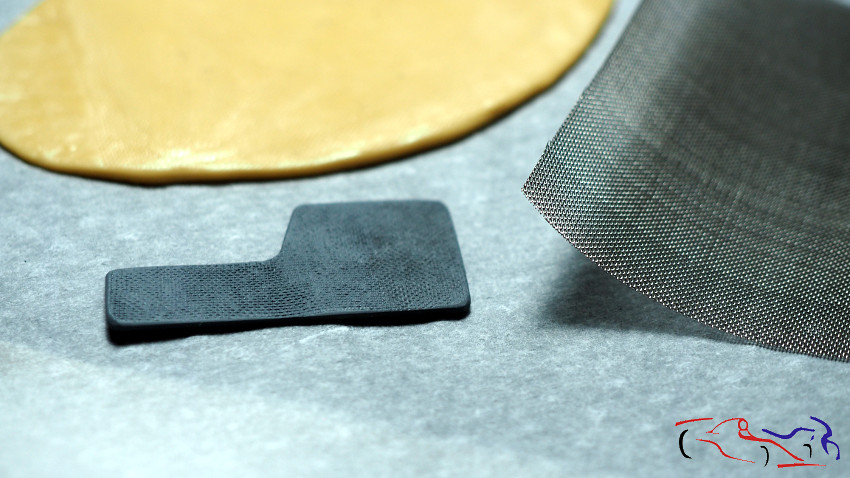
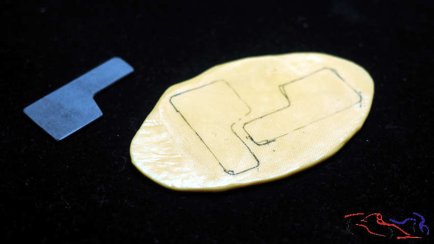
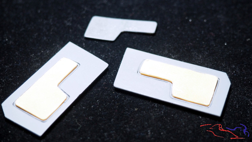
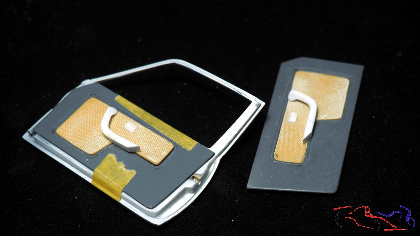
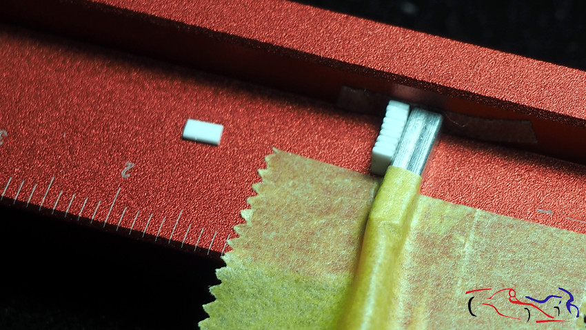
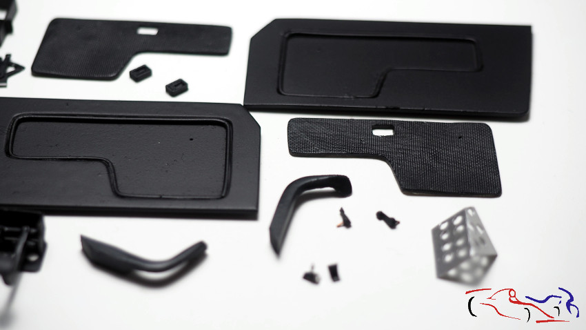
Pasamos al guarnecido de las puertas, que lo dejamos a falta de poner la parte central. Viendo fotos de un M3 de la escudería Bigazzi, que es el que llevaba Perez Sala en esta carrera, ese interior era como un tapizado de sofá, como si fuese tela. Y pensando como hacerlo, vi que las rejillas de Tameo eran muy parecidas y me puse con ello. Con masilla epoxy, hice una bola que al ponerla entre dos trozos de papel de hornear (de cocina), y pasándole un rodillo (el mango gordo de un cutter), logrè que fuera lo más fina posible. Una vez afinada, le puse la malla encima, y le volví a pasar el mango del cutter para que el entramado se marcara en la masilla. El siguiente paso, una vez seca, fue marcarla con la muestra y cortarla con exceso, para afinarla con limas y lijas. a su vez, también le rebajé el grosor lo más que pude para que se enrasara con el resto del guarnecido.
We moved on to the door trim, which we left unfinished except for the center section. Looking at photos of a Bigazzi M3, the one Perez Sala was driving in this race, the interior was like sofa upholstery, almost like fabric. Thinking about how to replicate it, I saw that Tameo’s grilles were very similar, so I got to work. Using epoxy putty, I made a ball, placed it between two pieces of parchment paper, and rolled it out with a roller (the thick handle of a utility knife) until it was as thin as possible. Once thinned, I placed the mesh on top and rolled it again with the utility knife handle to imprint the pattern onto the putty. The next step, once it was dry, was to trace it with the sample and cut off the excess, then smooth it down with files and sandpaper. I also reduced its thickness as much as possible so it would be flush with the rest of the trim.
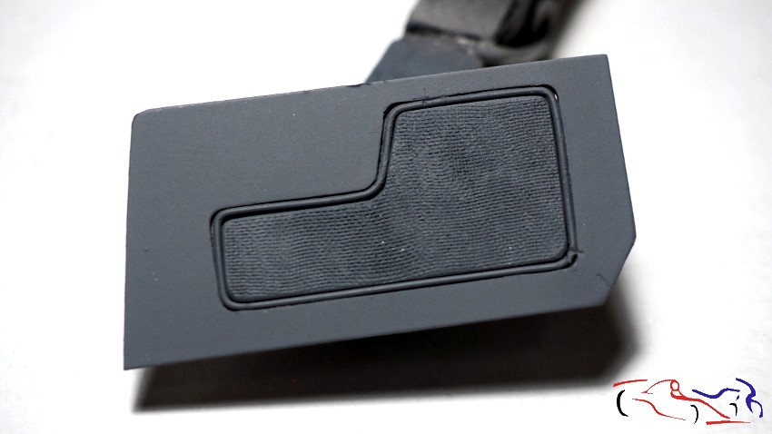
Incluyo una foto posterior, para que se vea como queda el guarnecido imprimado, con su trama en el centro:
I’ve included a later photo so you can see how the primed trim looks, with its pattern in the center:
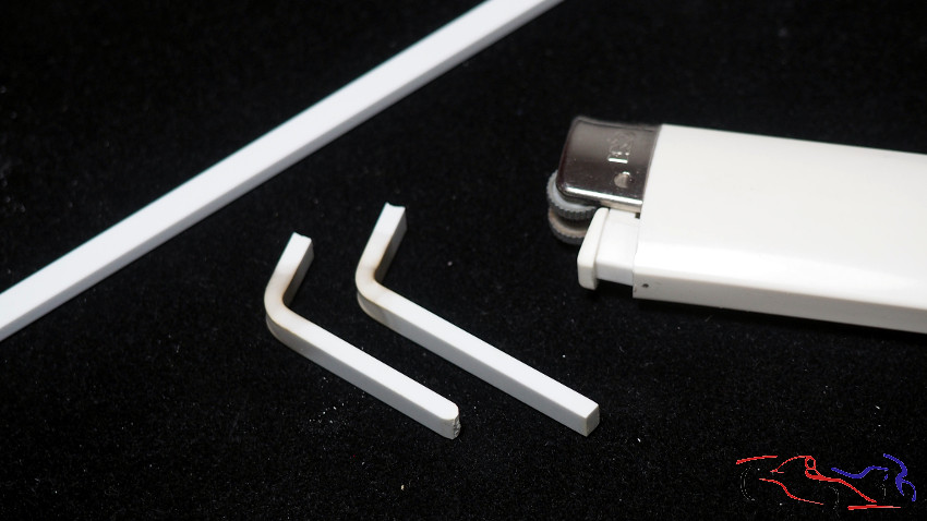
El siguiente paso era hacer los tiradores (o reposabrazos). Tomé varilla de plástico, que doblé con calor, y después, tocaba cortar y modelar con limas y lijas, dando la forma correcta. Podemos ver en la segunda foro, la pieza de resina que hice con masilla epoxy.
The next step was to make the handles (or armrests). I took plastic rod, which I bent with heat, and then cut and shaped it with files and sandpaper, giving it the correct form. You can see the resin piece I made with epoxy putty in the second photo.
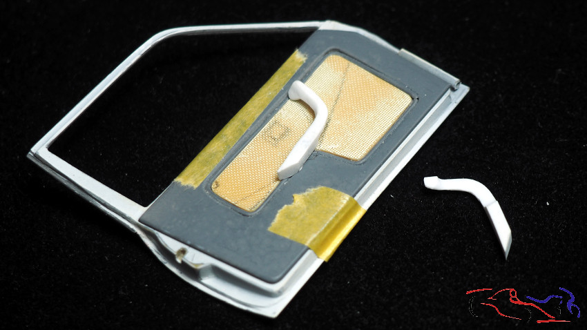
Continuamos con más piezas del guarnecido, y ahora es el turno del picaporte. Lo hice en plástico, agujereando posteriormente su lugar en la pieza de masilla epoxy. Para hacerlo y que quedaran en el mismo sitio, junté las piezas de las dos puertas. Se puede observar que no siempre hacemos las piezas del mismo tamaño…..
We continue with more trim pieces, and now it’s the door handle’s turn. I made it from plastic, later drilling holes for it in the epoxy putty piece. To make sure they were in the same place, I joined the pieces from both doors. You can see that we don’t always make the pieces the same size…
Y aquí vemos como queda el conjunto superpuesto. Falta el elevalunas, que también está en camino!!
And here’s how the assembly looks when it’s stacked up. The window regulator is missing, but it’s on its way!
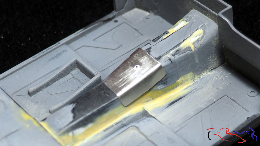
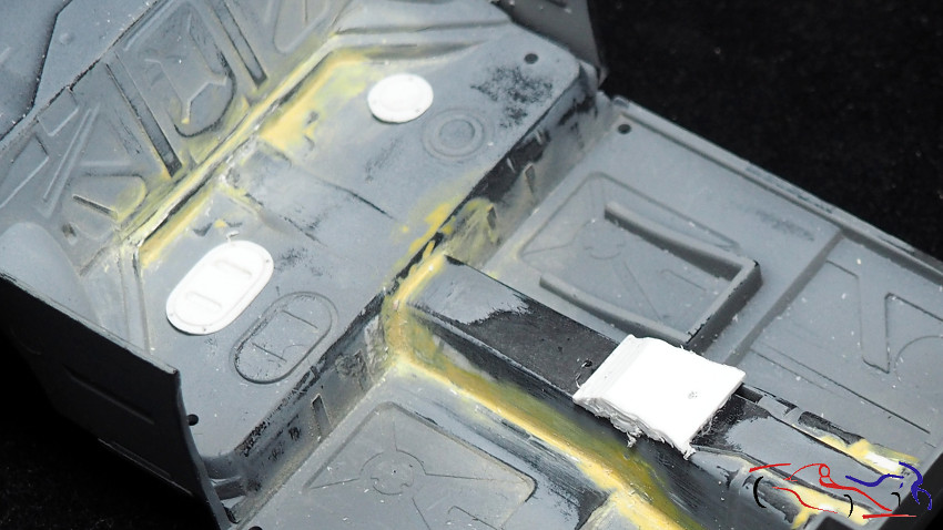
Pasamos al cockpit. Justo donde va la palanca de cambios, el coche lleva un refuerzo, que hice con capsula de botella de vino. Pero el kit tenía una forma no correcta, ya que en el coche real, el cambio de plano en el tunel de la transmisión más retrasado. Por tanto, añadimos varios trozos de láminas de plástico pegadas entre ellas. Aprovechamos a eliminar los registros de la parte trasera, para fabricar unos desde cero. Una vez seco el pegamento, lo limo y le pongo masilla UV por todos lados, que hago curar con la luz correspondiente.
We moved on to the cockpit. Right where the gearshift is, the car has a reinforcement, which I made from a wine bottle capsule. But the kit was the wrong shape, since in the real car, the plane change in the transmission tunnel is further back. Therefore, we added several pieces of plastic sheeting glued together. We took the opportunity to remove the access panels at the rear, to make new ones from scratch. Once the glue was dry, I sanded it down and applied UV putty all over, which I cured under the appropriate light.
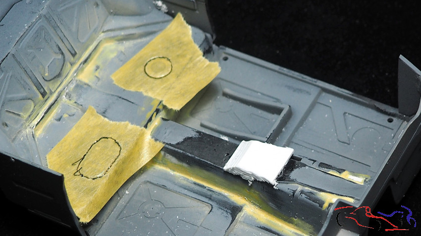
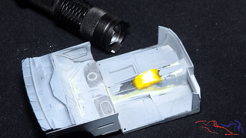
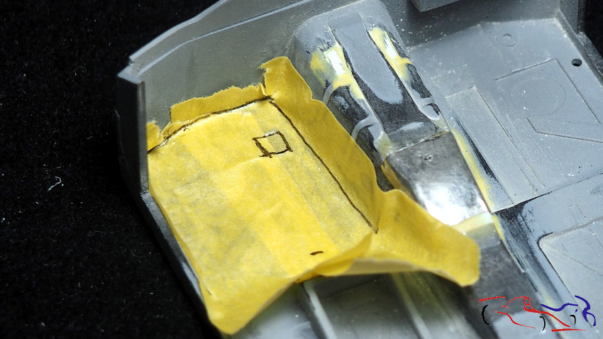
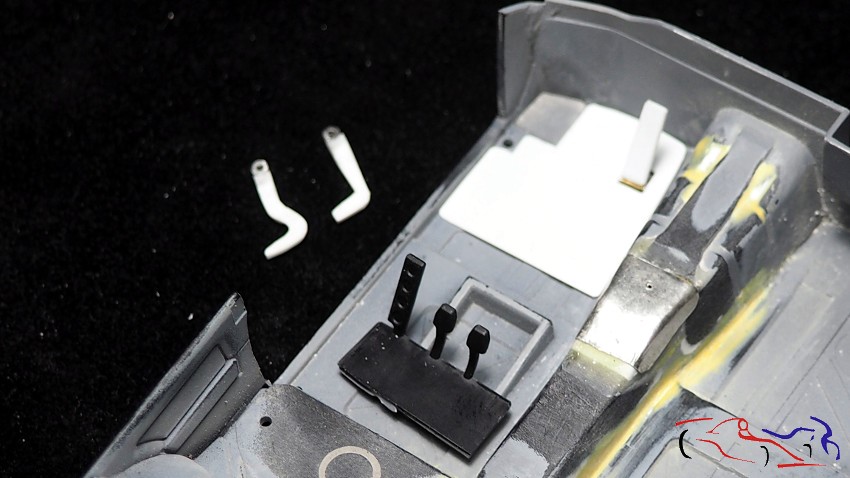
Una vez lijada la resina UV y con la pieza pegada, necesitamos hacer los pedales y el reposapies. EMpezando por este último, hacemos una máscara marcando los bordes de corte asi como el lugar donde va el acelerador, y el hueco a la izquierda donde va el reposapies del pie izquierdo. Lo pasamos a una lámina de plástico y vemos su encaje. A su vez comenzaamos a dar forma a los pedales, teniendo el pedal de embrague y freno en un conjunto, y el acelerador por separado. Estos se han realizado con plástico tallado, tiras y redondos de plástico, y tubos de metal.
Once the UV resin has been sanded and the piece glued in place, we need to make the pedals and the footrest. Starting with the footrest, we make a mask, marking the cutting edges as well as the location for the accelerator and the space on the left for the left footrest. We transfer this to a sheet of plastic and check how it fits. Next, we begin shaping the pedals, keeping the clutch and brake pedals as a single unit, and the accelerator pedal as a separate unit. These were made with carved plastic, plastic strips and rounds, and metal tubing.
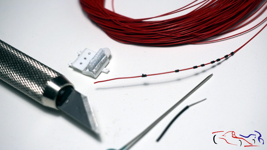
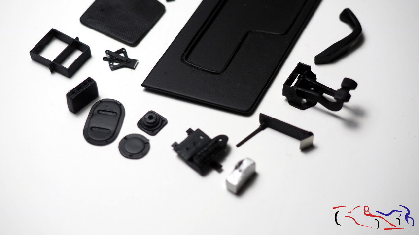
Continuamos con el interior, recreando la pieza donde van los fusibles, situada al lado del asiento, sobre el tunel central. Como son 8 fusibles, empiezo cortando y pegando una tira a la que he redondeado un poco las aristas, para que al pegarlos entre si, con ayuda de un soporte metálico, den la sensación de bloques distintos. Posteriormente, se añaden trocitos de redondo de plástico como si fueran las tapas donde van los propios fusibles, y se pega el cojunto a un soporte realizado en plástico como se ve en la segunda foto. Además, cada uno de esos fusibles lleva conectado en su parte inferior, un cable con una capucha de goma, que realizo con una camisa de cable que agrando e introduzco en el propio cable rojo. Más adelante lo cortaré y lo pegaré a cada fusible previo agujero hecho con broca de 0,3 mm.
We continue with the interior, recreating the fuse box located next to the seat, above the central tunnel. Since there are eight fuses, I start by cutting and gluing a strip of material with slightly rounded edges. This way, when glued together with a metal support, they’ll appear as distinct blocks. Next, small pieces of round plastic are added as fuse covers, and the assembly is glued to a plastic support, as seen in the second photo. Each fuse also has a wire with a rubber boot connected to its underside. I make this boot from a length of wire insulation, which I enlarge and insert into the red wire. Later, I’ll cut the rubber boot and glue it to each fuse after drilling a 0.3 mm hole.
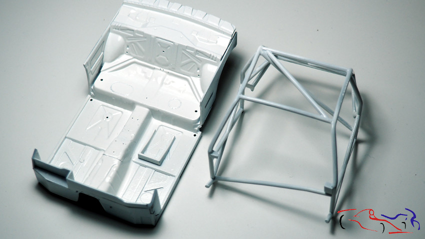
Mientras tanto, pinto de blanco LP de tamiya la cuna y el arco de seguridad, habiendo realizado agujeros en el cockpit para los distintos aparatos, entradas de cable o sopòrtes de lo que vaya a incluir.
Meanwhile, I paint the cradle and safety arch with Tamiya LP white, having made holes in the cockpit for the various devices, cable entry points or supports for whatever I am going to include.
Por último en este post, imprimo y pinto todas las piezas del interior. Destacar la trama del guarnecido de la puerta, o el repartidor de frenada de la ultima fotografia que me dio mucha guerra, tanto al hjacerlo como al montarlo en el cockpit. Pero esto ya lo cuento en el siguiente post.
Finally, in this post, I’m printing and painting all the interior parts. I’d like to highlight the door trim pattern and the brake bias adjuster in the last photo, which gave me a lot of trouble, both making it and mounting it in the cockpit. But I’ll talk about that in the next post.
Gracias por mirar y comentar!!
Thanks for watching and commenting!